What Is The Intake On A Car
Alright, let's dive into the intake system on your car. This is a crucial area to understand, whether you're troubleshooting performance issues, planning modifications, or just aiming to be a more informed car owner. Knowing the ins and outs of the intake system will empower you to diagnose problems, make informed decisions about upgrades, and even perform some repairs yourself. We're going to break down the key components, how they work together, and some common issues you might encounter. We have the complete intake system diagram available for download too, which will be a great visual aid as we go through this.
Key Specs and Main Parts
The intake system is responsible for delivering clean, filtered air to your engine for combustion. It's more than just a hole in the hood! Here's a breakdown of the main players:
- Air Filter: This is your engine's first line of defense against dirt, dust, and other contaminants. It's typically made of pleated paper or foam. A clogged air filter restricts airflow, hurting performance and fuel economy.
- Intake Tube(s): These tubes channel the air from the air filter housing to the throttle body (or carburetor on older vehicles). They're usually made of plastic or rubber.
- Mass Air Flow (MAF) Sensor (on fuel-injected vehicles): The MAF sensor measures the amount of air entering the engine. This information is crucial for the engine control unit (ECU) to calculate the correct amount of fuel to inject. A faulty MAF sensor can cause a variety of problems, including poor performance, rough idling, and a check engine light.
- Throttle Body: The throttle body controls the amount of air entering the intake manifold. It contains a throttle plate that opens and closes as you press the accelerator pedal.
- Intake Manifold: This is a complex component that distributes air evenly to each cylinder in the engine. It's typically made of aluminum or plastic. Some intake manifolds have variable geometry to optimize airflow at different engine speeds.
- Intake Valves: These valves open and close to allow air (or air-fuel mixture in older engines) into the cylinders during the intake stroke. They're part of the cylinder head.
- PCV (Positive Crankcase Ventilation) Valve: This valve is often connected to the intake manifold and is used to vent crankcase gases back into the intake system for combustion, reducing emissions.
These components work together to provide the engine with the necessary air for efficient combustion. Let's look at how this system functions.
How It Works
The process starts with the air filter. As the engine runs, it creates a vacuum in the cylinders during the intake stroke. This vacuum pulls air through the air filter, removing dirt and debris. The clean air then flows through the intake tube to the MAF sensor (if equipped). The MAF sensor measures the airflow and sends this data to the ECU.
Next, the air enters the throttle body. When you press the accelerator pedal, you're actually controlling the throttle plate in the throttle body. The more you open the throttle plate, the more air enters the intake manifold. The intake manifold then distributes the air evenly to each cylinder through individual runners. Finally, the intake valves open, allowing the air to enter the cylinders, where it mixes with fuel and is ignited to produce power.
The PCV valve plays a crucial role in emissions control. Blow-by gases from the crankcase, which contain unburned fuel and other contaminants, are routed back into the intake manifold through the PCV valve. This prevents these gases from being released into the atmosphere and helps maintain proper crankcase pressure.
Symbols – Explain Lines, Colors, and Icons
A typical intake system diagram will use various symbols to represent different components and connections. Here's a general guide:
- Solid Lines: Typically represent physical connections, such as hoses or tubes.
- Dashed Lines: Often indicate vacuum lines or control lines.
- Arrows: Show the direction of airflow.
- Colors: Can vary depending on the diagram, but often blue indicates air, red indicates fuel (in older carbureted systems), and green or yellow may indicate vacuum lines.
- Icons: Standardized icons are used to represent components like the air filter, MAF sensor, throttle body, and other parts. Refer to the diagram's legend for specific definitions.
Real-World Use – Basic Troubleshooting Tips
Understanding the intake system allows you to diagnose a variety of common problems. Here are a few troubleshooting tips:
- Poor Performance/Rough Idle: Check for vacuum leaks. Listen for hissing sounds around the intake manifold, hoses, and connections. A vacuum leak allows unmetered air into the engine, disrupting the air-fuel mixture.
- Check Engine Light (CEL): Use an OBD-II scanner to read the trouble codes. Codes related to the MAF sensor, throttle position sensor, or oxygen sensors can often point to intake system issues.
- Reduced Fuel Economy: A dirty air filter or a faulty MAF sensor can negatively impact fuel economy. Replace the air filter regularly and consider cleaning the MAF sensor (using a specialized MAF sensor cleaner) if it's suspected to be dirty.
- Whistling Noise: Could be an indication of air leak in the intake. Check the connections and make sure all bolts are properly torqued.
Vacuum leaks are a common culprit for many intake-related problems. You can use a smoke machine to help identify vacuum leaks. The smoke will escape from any leaks in the system, making them easy to spot.
Safety – Highlight Risky Components
Working on the intake system generally isn't considered high-risk, but there are a few safety precautions to keep in mind:
- Hot Surfaces: The intake manifold and other engine components can get extremely hot. Allow the engine to cool completely before working on the intake system.
- Electrical Connections: Disconnect the battery before working on any electrical components, such as the MAF sensor or throttle position sensor.
- Flammable Cleaners: Use caution when using cleaners to clean the throttle body or MAF sensor. Make sure the area is well-ventilated and avoid using flammable cleaners near open flames or sparks.
- Moving Parts: Keep hands and loose clothing away from the throttle linkage and other moving parts when the engine is running.
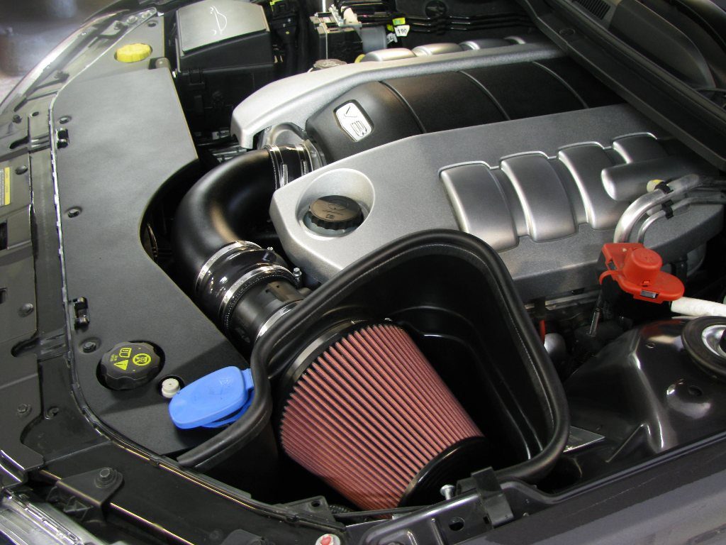
Special Note on Modified Intakes: If you've installed an aftermarket intake system, it's crucial to understand how it differs from the stock system. Some aftermarket intakes require adjustments to the ECU tuning to ensure proper air-fuel ratios. Improper tuning can lead to performance problems and even engine damage.
The intake system is a vital part of your engine. Understanding its components and how they work can save you time and money on repairs and allow you to make informed decisions about modifications. With the information provided here and the downloadable diagram we have, you should be well-equipped to tackle many intake-related issues. Remember to consult your vehicle's repair manual for specific instructions and torque specifications.