What Is Vdc In A Nissan
Let's dive into understanding the Vehicle Dynamic Control (VDC) system in your Nissan. If you're into DIY car repairs, modifications, or just want to understand your vehicle better, knowing how the VDC system works and having access to its wiring diagram is invaluable. This article will break down the VDC system, its components, and how to interpret its wiring diagram, equipping you with the knowledge for troubleshooting and repairs.
Purpose of Understanding the VDC Diagram
Why bother understanding the VDC diagram? Well, it's your roadmap to understanding a critical safety system. Here’s why it matters:
- Troubleshooting: When the VDC light illuminates on your dashboard, a wiring diagram helps you pinpoint the fault instead of blindly replacing parts.
- Repairs: Accurate repairs are impossible without knowing how the components interconnect. A diagram ensures you're working on the correct circuits.
- Modifications: If you're adding aftermarket components like bigger tires, suspension upgrades, or even engine modifications, understanding how they might impact the VDC is crucial for safety.
- General Knowledge: Expanding your knowledge about your vehicle empowers you to communicate effectively with mechanics and make informed decisions about maintenance.
Key Specs and Main Parts of the VDC System
The VDC system is an advanced electronic stability control system designed to prevent skidding and loss of control, especially in adverse conditions. It does this by selectively applying brakes to individual wheels and adjusting engine output.
Main Components:
- VDC/ABS Control Unit: This is the brain of the system. It receives information from various sensors, processes it, and sends commands to the actuators. It often integrates the ABS (Anti-lock Braking System) functionality.
- Wheel Speed Sensors: Located at each wheel, these sensors provide real-time data on wheel rotation speed. This information is crucial for detecting wheel slip or lock-up.
- Steering Angle Sensor: Mounted on the steering column, this sensor measures the driver's intended steering direction.
- Yaw Rate Sensor: Measures the vehicle's rotation around its vertical axis (yaw). This helps determine if the car is rotating more or less than the driver intended.
- Lateral G-Force Sensor (Accelerometer): Measures the lateral acceleration acting on the vehicle. This helps the VDC determine if the car is starting to slide sideways.
- Brake Actuator (Hydraulic Control Unit): This unit contains valves and a pump that control brake pressure to individual wheels, as commanded by the VDC control unit.
- Engine Control Module (ECM): The VDC system can communicate with the ECM to reduce engine power in certain situations, helping to prevent wheel spin.
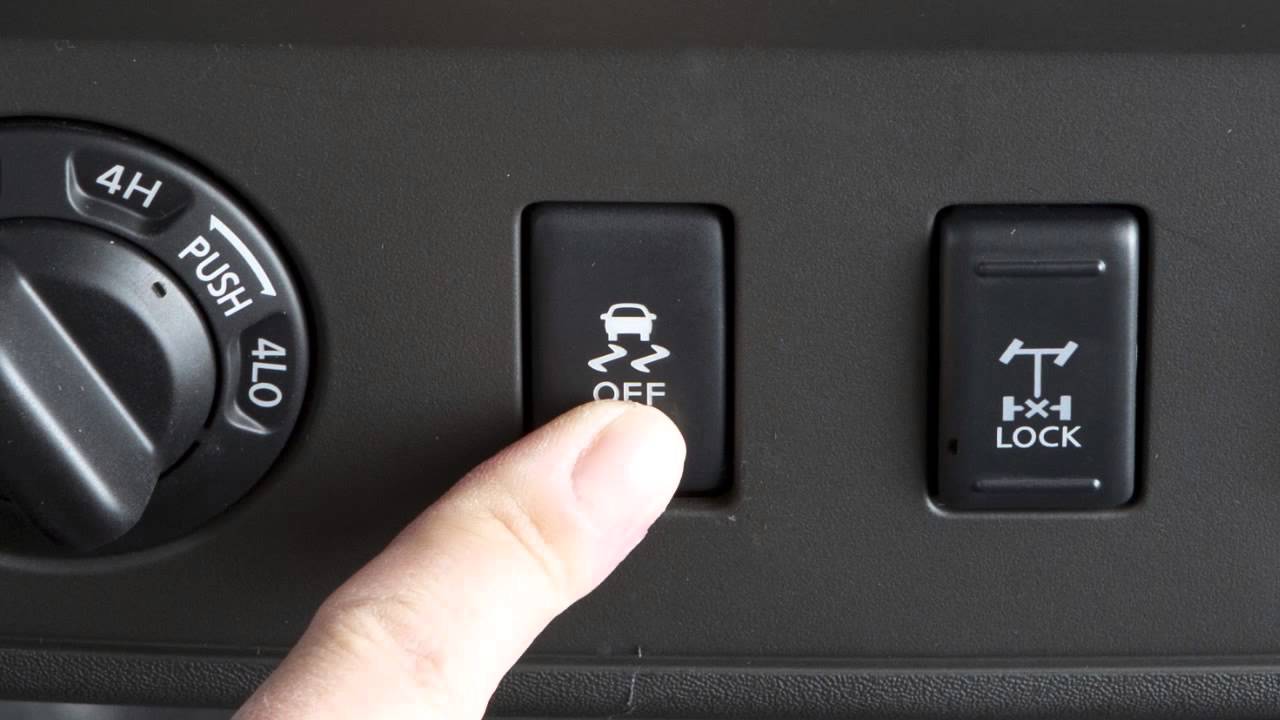
- VDC OFF Switch: Allows the driver to disable the VDC system (usually in specific situations like deep snow).
Key Specs: These vary depending on the Nissan model and year. Common specs you might find referenced in a diagram include:
- Voltage: Most sensors and actuators operate on the vehicle's standard 12V DC system.
- Resistance Values: Sensor resistance values are critical for diagnosing sensor malfunctions. The diagram might show expected resistance ranges for specific sensors.
- Signal Types: Sensors can output analog voltage signals, digital signals (like PWM - Pulse Width Modulation), or communicate via CAN (Controller Area Network) bus.
Symbols and Conventions in the VDC Diagram
Understanding the symbols in the VDC diagram is essential for interpreting the information it conveys. Here's a breakdown of common elements:
- Lines: Represent wires. Solid lines indicate a direct connection, while dashed lines often indicate a shielded wire or a connection through a connector.
- Colors: Wires are color-coded. Refer to the legend on the diagram to understand what each color represents (e.g., Red = Battery, Black = Ground, Blue = Signal).
- Connectors: Represented by squares, circles, or other shapes. They indicate where wires connect to each other. Connector numbers are usually labeled (e.g., E12, B34).
- Components: Represented by schematic symbols specific to the component (e.g., resistor symbol for a wheel speed sensor, relay symbol for a brake actuator relay).
- Grounds: Usually represented by a triangle or a series of horizontal lines, indicating a connection to the vehicle's chassis ground.
- Fuses: Represented by a jagged line inside a rectangle. The fuse amperage rating is usually indicated.
- Abbreviations: Common abbreviations include ECU (Engine Control Unit), ABS (Anti-lock Braking System), VDC (Vehicle Dynamic Control), ECM (Engine Control Module), CAN (Controller Area Network).
Example: A line colored green with the label "VSS-FL" running from the front left wheel speed sensor to the VDC control unit would indicate the signal wire carrying the front left wheel speed sensor data to the control unit.
How the VDC System Works
The VDC system constantly monitors various sensors to detect potential loss of control. Here's a simplified explanation:
- Data Acquisition: The wheel speed sensors, steering angle sensor, yaw rate sensor, and lateral G-force sensor provide real-time data to the VDC control unit.
- Data Analysis: The VDC control unit compares the driver's intended steering direction (from the steering angle sensor) with the vehicle's actual movement (from the yaw rate and lateral G-force sensors).
- Loss of Control Detection: If a discrepancy is detected (e.g., the car is rotating more than the driver is steering), the VDC system determines that the vehicle is starting to skid.
- Corrective Action: The VDC control unit activates the brake actuator to selectively apply brakes to individual wheels. It might also communicate with the ECM to reduce engine power. The goal is to counteract the skid and bring the vehicle back under control.
Example: If the car is oversteering (rear end sliding out), the VDC might apply the brake to the outside front wheel. This creates a yaw moment that helps to pull the car back into line.
Real-World Use: Basic Troubleshooting Tips
Here are a few basic troubleshooting tips using the VDC diagram:
- VDC Light On: Use a scan tool to retrieve the Diagnostic Trouble Code (DTC). The DTC will point to a specific sensor or circuit. Refer to the wiring diagram to locate that sensor or circuit.
- Wheel Speed Sensor Fault: Use a multimeter to check the sensor's resistance. Compare the measured value to the expected range in the service manual. Also, check the wiring for continuity and shorts to ground.
- Steering Angle Sensor Fault: Verify the sensor's calibration. Sometimes, a simple recalibration is all that's needed. Check the wiring for damage.
- Communication Errors: If you see CAN bus communication errors related to the VDC, check the CAN bus wiring for shorts or opens. Also, ensure that all modules connected to the CAN bus are properly powered and grounded.
Important Note: Always start with the simplest checks first, such as verifying that the battery voltage is correct and that all fuses are intact.
Safety Precautions
Working on the VDC system involves potentially hazardous components. Observe these safety precautions:
- Disconnect the Battery: Always disconnect the negative battery terminal before working on any electrical components.
- High-Pressure Brake Fluid: The brake actuator contains high-pressure brake fluid. Depressurize the system according to the service manual before disconnecting any brake lines. Brake fluid is corrosive and can damage paint.
- Airbag System: The VDC system is often integrated with the airbag system. Never probe or tamper with airbag wiring unless you are specifically trained to do so. Accidental airbag deployment can cause serious injury.
- Proper Tools: Use the correct tools for the job. Avoid using damaged or makeshift tools.
- Consult the Service Manual: Always refer to the Nissan service manual for specific instructions and safety precautions related to your vehicle model.
The VDC system is complex, and some diagnostics and repairs require specialized equipment and expertise. If you're not comfortable performing a particular task, it's best to seek assistance from a qualified mechanic.
We have the VDC wiring diagrams readily available for download to assist in your work.