What To Do If Abs Light Comes On
Decoding Your ABS Light: A DIY Mechanic's Guide
The appearance of your Anti-lock Braking System (ABS) warning light can be unsettling. It signals a problem with a crucial safety system designed to prevent wheel lockup during hard braking, allowing you to maintain steering control. While a lit ABS light doesn’t necessarily mean your brakes will fail entirely, it does indicate that the ABS functionality is compromised. This article provides an in-depth look at the ABS system, common causes for the warning light, and troubleshooting steps for the intermediate DIY mechanic.
Purpose of Understanding Your ABS System
This guide aims to empower you with the knowledge to diagnose and potentially repair ABS-related issues yourself. Understanding the system allows for informed decision-making, whether you're tackling a repair directly, communicating effectively with a mechanic, or simply wanting to ensure your vehicle's safety systems are functioning correctly. This knowledge is invaluable for regular maintenance, preventative care, and saving money on costly diagnostic fees.
Key Specs and Main Parts of the ABS
The ABS is a sophisticated system comprised of several key components, working in unison to prevent wheel lockup. Here’s a breakdown:
- Wheel Speed Sensors: These sensors, typically located at each wheel hub, monitor the rotational speed of each wheel. They transmit this data to the ABS control module.
- ABS Control Module (EBCM): This is the "brain" of the ABS. It receives data from the wheel speed sensors, analyzes it for signs of impending wheel lockup, and controls the hydraulic modulator. This is sometimes also referred to as the ECU (Electronic Control Unit).
- Hydraulic Modulator (HCU): This unit contains a series of valves and a pump that regulate the brake pressure to each wheel. Under normal braking, these valves are open, allowing brake pressure to flow freely. When the EBCM detects a wheel is about to lock up, it actuates the valves to reduce or hold pressure to that wheel.
- Brake Lines: These carry brake fluid from the master cylinder to the hydraulic modulator and then to the individual wheel calipers.
- Brake Calipers & Rotors: The calipers squeeze the brake pads against the rotors, creating friction to slow the vehicle.
Deciphering the ABS Wiring Diagram: Symbols and Lines
A wiring diagram is essential for troubleshooting electrical issues within the ABS system. Understanding the symbols and conventions used is critical:
- Lines: Lines represent wires connecting different components. The thickness of the line may sometimes indicate the gauge (thickness) of the wire.
- Colors: Wires are often color-coded. The diagram will typically include a legend identifying each color and its corresponding function. For instance, a green wire might be for a sensor signal, while a red wire might be for power.
- Symbols: Specific symbols represent different components:
- Resistors: A zig-zag line.
- Capacitors: Two parallel lines.
- Diodes: A triangle pointing to a vertical line.
- Grounds: A series of descending horizontal lines, indicating a connection to the vehicle's chassis.
- Fuses: A wavy line or a box with a number indicating its amperage rating.
- Relays: A coil and a switch mechanism.
- Connectors: Represented by circles or squares, indicating where wires connect to components or other wires.
Note: Wiring diagrams vary between manufacturers and models. Always use the specific diagram for your vehicle.
How the ABS Works: A Step-by-Step Explanation
The ABS system works in a closed-loop feedback system. Here's how it functions:
- Wheel Speed Monitoring: Wheel speed sensors constantly monitor the rotational speed of each wheel and send this data to the EBCM.
- Data Analysis: The EBCM analyzes the wheel speed data, looking for signs of impending wheel lockup. Wheel lockup occurs when a wheel stops rotating while the vehicle is still in motion.
- Pressure Modulation: If the EBCM detects a wheel is about to lock up, it signals the hydraulic modulator (HCU) to intervene. The HCU uses valves to rapidly reduce, hold, or increase brake pressure to the affected wheel. This cycle can happen multiple times per second.
- Maintaining Steering Control: By preventing wheel lockup, the ABS allows the driver to maintain steering control during hard braking. The wheels continue to rotate, providing traction and allowing the driver to steer around obstacles.
Real-World Troubleshooting: Diagnosing a Lit ABS Light
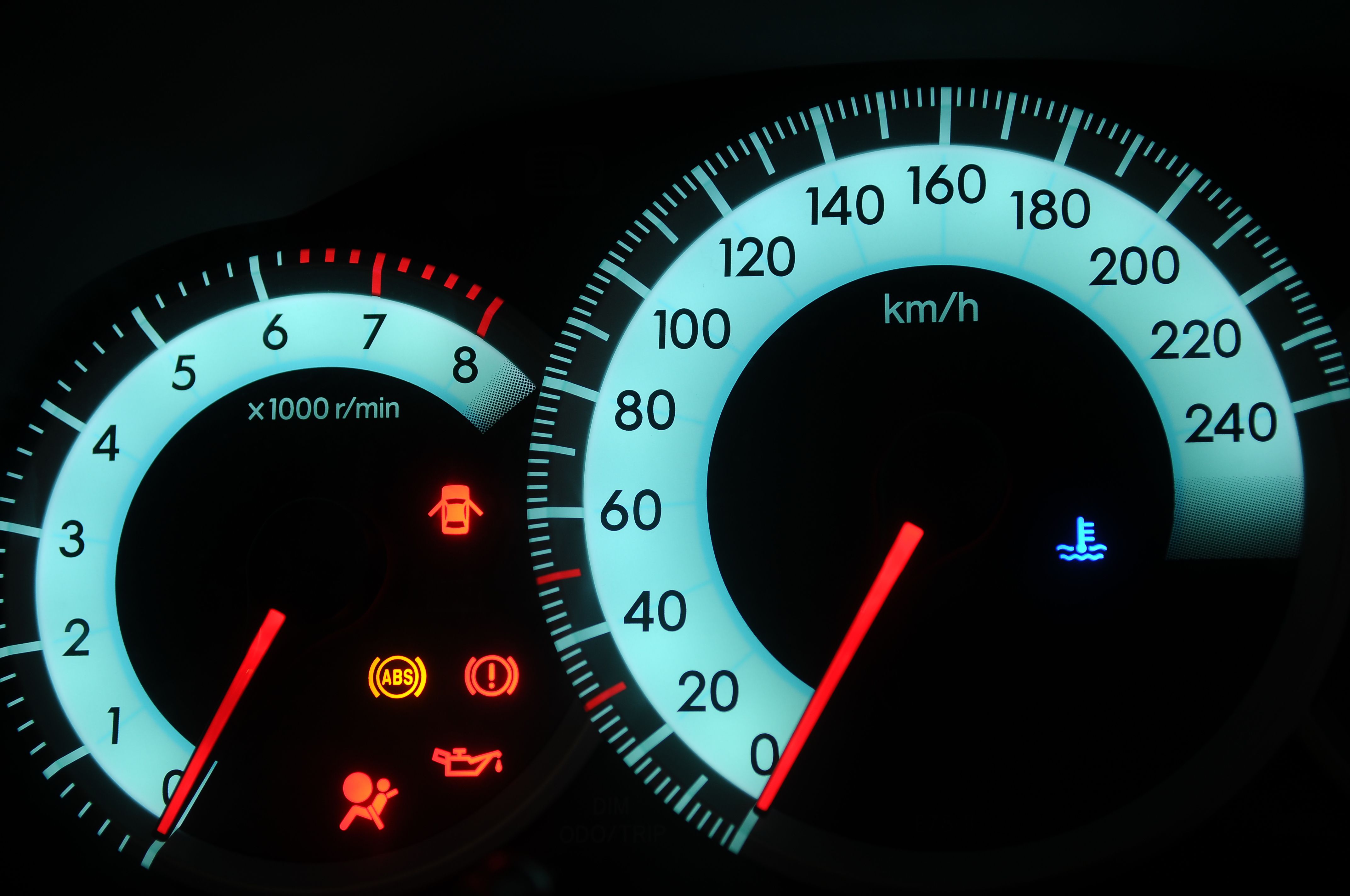
When your ABS light illuminates, it indicates a fault within the system. Here are some basic troubleshooting steps:
- Visual Inspection: Start with a visual inspection of all ABS components. Check for damaged wiring, loose connectors, or signs of brake fluid leaks around the calipers and hydraulic modulator.
- Check the Brake Fluid Level: Low brake fluid can sometimes trigger the ABS light. Ensure the brake fluid reservoir is filled to the proper level.
- Scan for Trouble Codes: The most effective way to diagnose the ABS light is to use an OBD-II scanner (capable of reading ABS codes). Connect the scanner to your vehicle's diagnostic port and retrieve any stored Diagnostic Trouble Codes (DTCs). These codes provide valuable information about the nature of the fault. Common codes relate to wheel speed sensor failures, hydraulic modulator problems, or issues with the EBCM.
- Wheel Speed Sensor Testing: If the DTC points to a wheel speed sensor, you can test the sensor using a multimeter. Measure the sensor's resistance and compare it to the manufacturer's specifications. You can also check the sensor's signal output while rotating the wheel.
- Fuse Check: Locate the ABS fuse in your vehicle's fuse box and inspect it for damage. A blown fuse can disable the ABS system.
Example: A code like C0031 indicates a fault with the left front wheel speed sensor circuit.
Safety First: Handling ABS Components
Working on the ABS system involves handling brake fluid and electrical components. Exercise caution to prevent injury and damage to the system.
- Brake Fluid: Brake fluid is corrosive and can damage paint and other surfaces. Avoid contact with skin and eyes. If contact occurs, flush immediately with water.
- Electrical Components: Always disconnect the negative battery terminal before working on any electrical components in the ABS system. This prevents accidental short circuits and potential damage to the EBCM. The EBCM is sensitive to static electricity. Use proper grounding techniques when handling it.
- Hydraulic Modulator: The hydraulic modulator contains high-pressure brake fluid. Use caution when disconnecting brake lines from the modulator. Bleed the brake system after making any repairs to the hydraulic system.
- Proper Tools: Using the correct tools is crucial. For example, using a flare nut wrench on brake lines prevents rounding the fittings.
Remember: If you are uncomfortable performing any of these procedures, consult a qualified mechanic.
We have a comprehensive ABS wiring diagram file available for download. This diagram can be an invaluable tool for diagnosing and repairing issues within your ABS system.