What Year Did Obd2 Come Out
For the seasoned DIY mechanic or car enthusiast, understanding On-Board Diagnostics II (OBD2) is practically essential. It's the gateway to deciphering what your car's computer, the Engine Control Unit (ECU), is trying to tell you. A common question is, when did this system become standard? The answer, while seemingly straightforward, has some nuances. Generally, OBD2 became mandatory for all gasoline-powered passenger vehicles sold in the United States starting in 1996. However, some manufacturers began incorporating OBD2 features in their vehicles as early as 1994 and 1995.
Why Understanding OBD2 Matters
Think of OBD2 as your car's built-in health monitor. It's a standardized system, meaning that the same diagnostic tools and codes apply across a wide range of manufacturers and models. Knowing how OBD2 works and what its various components mean is invaluable for:
- Troubleshooting: Identify problems early, preventing more significant (and costly) repairs down the line.
- Repairing: Accurately diagnose issues before replacing parts. Nobody wants to throw parts at a problem hoping something sticks.
- Modding/Tuning: Monitoring engine performance when making modifications. This allows you to check that your modifications are effective and safe.
- Learning: Gain a deeper understanding of how your car works and the complex interactions between its various systems.
- Avoiding Unnecessary Repairs: Second opinions aren't cheap, but having the understanding of OBD2 can let you know if a shop is genuinely helping.
Understanding the intricate web of sensors, wires, and computer logic can seem daunting. Having a reference diagram makes all the difference when troubleshooting issues. We have such a diagram available for download, which will be an invaluable asset in your diagnostic endeavors.
Key Specs and Main Parts of the OBD2 System
The OBD2 system isn't just a plug; it’s a complex network of interconnected components. Here are some of the most important parts:
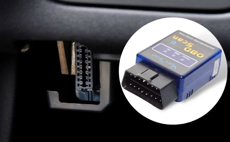
- Diagnostic Link Connector (DLC): This is the 16-pin connector, usually located under the dashboard, where you plug in your OBD2 scanner.
- Engine Control Unit (ECU): The brain of the operation. The ECU monitors sensor data, controls various engine functions, and stores diagnostic trouble codes (DTCs).
- Sensors: A multitude of sensors provide the ECU with data, including:
- Oxygen (O2) Sensors: Measure the oxygen content in the exhaust gas, crucial for fuel mixture control.
- Mass Air Flow (MAF) Sensor: Measures the amount of air entering the engine.
- Manifold Absolute Pressure (MAP) Sensor: Measures the pressure in the intake manifold.
- Throttle Position Sensor (TPS): Monitors the position of the throttle plate.
- Crankshaft Position Sensor (CKP): Determines the position and speed of the crankshaft.
- Camshaft Position Sensor (CMP): Determines the position of the camshaft.
- Actuators: These are devices controlled by the ECU to affect engine operation, such as:
- Fuel Injectors: Control the amount of fuel injected into the cylinders.
- Ignition Coils: Provide the spark to ignite the air-fuel mixture.
- Idle Air Control (IAC) Valve: Regulates the amount of air entering the engine at idle.
- Diagnostic Trouble Codes (DTCs): Standardized codes that the ECU stores when a problem is detected. These codes help pinpoint the source of the issue. These are based on SAE J2012 standards.
- OBD2 Scanner: A handheld device or software application used to read DTCs, view live data, and perform other diagnostic functions.
The OBD2 standard mandates specific communication protocols. Common protocols include:
- SAE J1850 PWM (Pulse Width Modulation): Used by Ford.
- SAE J1850 VPW (Variable Pulse Width): Used by GM.
- ISO 9141-2: Used by Chrysler, European, and Asian vehicles.
- ISO 14230 (KWP2000): Used by Chrysler, European, and Asian vehicles.
- CAN (Controller Area Network): The most modern protocol, used by virtually all vehicles manufactured after 2008.
Understanding OBD2 Symbols and Diagrams
Electrical diagrams, sometimes called wiring schematics, are essential for tracing circuits and understanding how different components interact. Our downloadable diagram provides a visual representation of the OBD2 system. Let’s break down some common symbols:
- Lines: Represent wires. A thicker line may indicate a larger gauge wire.
- Colors: Wires are often color-coded to help identify them. A key or legend will specify what each color represents (e.g., Red = Power, Black = Ground, etc.).
- Circles: Can represent connections, sensors, or switches. The shape inside the circle will differentiate these.
- Squares/Rectangles: Often represent components like the ECU, relays, or fuses.
- Ground Symbols: Indicate a connection to the vehicle's chassis ground.
- Connector Symbols: Show where wires connect to plugs or sockets.
- Arrows: May indicate the direction of current flow or signal flow.
Pay attention to the wire gauge, specified next to the wire color. Wire gauge is a measurement of wire thickness; thicker wires are generally used for higher current circuits. Also, look out for splices in the wiring. This indicates that one wire splits off into two or more wires. A well-organized wiring diagram is essential for effective troubleshooting. The diagram will also include references to component locations within the vehicle.
How OBD2 Works
The OBD2 system is constantly monitoring various parameters related to engine performance and emissions. The process works something like this:
- Sensors Collect Data: Sensors throughout the engine and exhaust system continuously monitor parameters like air flow, oxygen levels, temperature, and pressure.
- Data Transmission: Sensor data is sent to the ECU.
- Data Processing: The ECU compares the sensor data to pre-programmed values and algorithms.
- Fault Detection: If the ECU detects a deviation from the expected values (a fault), it stores a DTC in its memory.
- Malfunction Indicator Lamp (MIL): In many cases, the ECU will illuminate the MIL (also known as the "Check Engine" light) on the dashboard to alert the driver to a problem.
- Diagnostic Access: A technician or DIYer can connect an OBD2 scanner to the DLC to retrieve the stored DTCs and view live data.
Real-World Use: Basic Troubleshooting Tips
Here are some basic troubleshooting tips when using an OBD2 scanner:
- Read DTCs: The first step is to read the DTCs stored in the ECU. Record all codes.
- Research the Codes: Use a reliable online database or repair manual to look up the meaning of each DTC.
- Verify the Problem: Before replacing any parts, verify that the problem is actually present. Check for obvious issues like loose connections, damaged wires, or vacuum leaks.
- Clear the Codes: After making repairs, clear the DTCs and monitor the system to see if the codes return. This ensures that the repair was effective.
- Live Data: Use the live data function of the scanner to monitor sensor readings in real-time. This can help you identify intermittent problems or pinpoint faulty sensors. For example, does the O2 sensor read consistently high or low? Is the MAF sensor reading correctly at idle?
For example, a P0171 code (System Too Lean, Bank 1) could indicate a vacuum leak, a faulty MAF sensor, or a fuel delivery problem. Live data can help narrow down the possibilities. The downloadable diagram can help you trace the circuits related to the MAF sensor or fuel injectors.
Safety Considerations
Working on your car can be dangerous if you're not careful. Keep these safety tips in mind:
- Disconnect the Battery: Disconnect the negative battery terminal before working on any electrical components.
- Be Careful with Fuel: Fuel is highly flammable. Work in a well-ventilated area and avoid sparks or open flames.
- Hot Exhaust: Exhaust components can be extremely hot. Allow the engine to cool down completely before working on the exhaust system.
- High Voltage: Ignition systems operate at high voltage. Avoid touching ignition components when the engine is running. Be especially cautious around ignition coils, as they can deliver a painful (and potentially dangerous) shock.
- Proper Tools: Use the correct tools for the job. Don't try to force anything or use makeshift tools.
Always consult a qualified mechanic if you are unsure about any aspect of the repair process.
Understanding the OBD2 system is crucial for modern car owners and DIY mechanics. With a solid grasp of the system's components, functions, and troubleshooting techniques, you can save time, money, and frustration. Remember, we have a downloadable diagram available that can be a valuable resource in your diagnostic and repair endeavors. Don't hesitate to use it as a reference guide as you dive deeper into the world of automotive diagnostics.