01 Ford Explorer Sport Trac Fuse Box Diagram
Welcome, fellow gearheads! Today, we're diving deep into the heart of your 2001 Ford Explorer Sport Trac's electrical system: the fuse box diagram. This isn't just a pretty picture; it's the roadmap to diagnosing and resolving electrical gremlins that can plague any vehicle. Whether you're tackling a blown fuse, adding aftermarket accessories, or just trying to understand your truck's inner workings, understanding this diagram is essential.
Why This Diagram Matters
Think of your Sport Trac's fuse box as the central nervous system of its electrical system. Fuses are sacrificial components designed to protect more expensive and crucial parts of your truck from overcurrent conditions. When a circuit draws too much amperage (usually due to a short circuit or a faulty component), the fuse blows, interrupting the electrical flow and preventing damage. A fuse box diagram is crucial for:
- Troubleshooting Electrical Issues: Identifying the blown fuse responsible for a malfunctioning component (e.g., headlights, radio, power windows).
- Adding Aftermarket Accessories: Properly tapping into the electrical system to power lights, stereos, or other accessories without overloading existing circuits.
- General Electrical System Understanding: Gaining insight into how the different circuits in your Sport Trac are connected and protected.
- Preventing Further Damage: Identifying a blown fuse quickly can prevent more serious electrical problems from developing.
Key Specs and Main Parts of the 2001 Sport Trac Fuse Boxes
The 2001 Ford Explorer Sport Trac typically has two main fuse box locations:
Under-Dash Fuse Box (Interior)
Located inside the cabin, usually beneath the dashboard on the driver's side. This fuse box primarily controls interior circuits, such as:
- Interior lighting
- Radio
- Power windows and locks
- Windshield wipers
- Instrument panel
- And other cabin electronics.
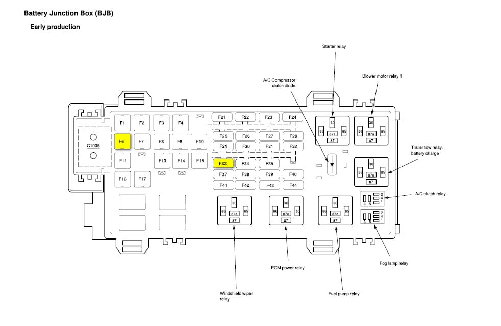
Power Distribution Box (Under the Hood)
Found in the engine compartment, usually near the battery. This box houses larger fuses and relays, controlling high-current circuits like:
- Headlights
- Taillights
- Fuel pump
- Ignition system
- Starter motor
- Anti-lock braking system (ABS)
- And other critical engine and vehicle systems.
Key Specs: The diagram will typically list the following for each fuse:
- Fuse Number: A unique identifier for each fuse location.
- Amperage Rating: The maximum current (measured in Amperes or "Amps") the fuse can handle before blowing. Common ratings include 5A, 7.5A, 10A, 15A, 20A, 25A, 30A, and 40A.
- Circuit Protected: A brief description of the component or system the fuse protects.
Understanding Fuse Box Diagram Symbols
Fuse box diagrams aren't just random lines and boxes. They use specific symbols to convey information efficiently. Here's a breakdown:
Lines and Connections
- Solid Lines: Represent a direct electrical connection between components.
- Dashed Lines: Often indicate a ground connection or a secondary circuit path.
- Junctions (Dots): Where two or more lines intersect, indicating a common connection point.
Colors
While not always consistent across every diagram variation, color-coding can be helpful. Here are some common color conventions (always double-check with your specific diagram):
- Red: Typically indicates a power source (e.g., battery positive).
- Black: Usually represents ground (battery negative).
- Other Colors (Blue, Yellow, Green, etc.): Indicate different circuits or signal paths. Consult the diagram legend for specifics.
Icons and Abbreviations
Fuse box diagrams use standard icons and abbreviations to represent components. Some common examples include:
- Headlight Icon: Represents the headlight circuit.
- Horn Icon: Indicates the horn circuit.
- "ECU" or "PCM": Refers to the Engine Control Unit or Powertrain Control Module (the car's computer).
- "ABS": Stands for Anti-lock Braking System.
- "ACC": Accessory power.
Always refer to the diagram's legend for a complete list of symbols and abbreviations.
How It Works: The Electrical Flow
The electrical system in your Sport Trac works as a closed loop. Power flows from the battery, through a fuse (for protection), to the component (e.g., a light bulb), and then back to the battery through a ground connection. The fuse is the weakest link in this loop. If there's an overcurrent condition, the thin wire inside the fuse melts, breaking the circuit and preventing damage to the more expensive component. By consulting the fuse box diagram, you can quickly identify which fuse protects a specific circuit and replace it if necessary.
Real-World Use: Basic Troubleshooting Tips
Here's how to use the fuse box diagram to diagnose and fix common electrical problems:
- Identify the Problem: What component isn't working? (e.g., the radio, the power windows).
- Consult the Diagram: Locate the fuse that protects the malfunctioning component using the diagram.
- Inspect the Fuse: Visually inspect the fuse. A blown fuse will have a broken filament inside. Some people use a multimeter to check for continuity, which is the most reliable method.
- Replace the Fuse: Use a fuse puller (often found in the fuse box) to remove the blown fuse. Replace it with a new fuse of the exact same amperage rating. Using a higher amperage fuse can overload the circuit and cause serious damage or even a fire.
- Test the Component: After replacing the fuse, test the component to see if it's working.
- If the Fuse Blows Again: If the new fuse immediately blows again, there's a short circuit in the wiring or a faulty component. This requires further diagnosis, potentially involving a multimeter and a wiring diagram. It's often best to consult a qualified mechanic in this situation.
Safety First: Risky Components and Precautions
Working with electrical systems can be dangerous. Always take the following precautions:
- Disconnect the Battery: Before working on any electrical component, disconnect the negative (-) battery cable to prevent accidental shorts or shocks.
- Use the Right Fuse: Never replace a fuse with a higher amperage rating. This can bypass the circuit protection and lead to overheating and fire.
- Avoid Working in Wet Conditions: Water and electricity are a dangerous combination.
- Be Careful Around Airbags: Some fuses control the airbag system. Improper handling can trigger the airbags, causing serious injury. If you suspect a problem with the airbag system, consult a qualified technician.
- High-Voltage Circuits: Be extremely cautious around the ignition system and other high-voltage circuits. These circuits can deliver a dangerous shock even with the battery disconnected.
Specifically, the circuits powering the ignition system, fuel pump, and airbags should be approached with utmost caution. Improper handling can lead to serious consequences.
Understanding the fuse box diagram empowers you to diagnose and resolve electrical issues in your 2001 Ford Explorer Sport Trac confidently and safely. By understanding the purpose, components, and symbols of the diagram, you can tackle basic electrical repairs and modifications with ease, saving time and money while gaining valuable knowledge of your vehicle's inner workings.
We have the complete 2001 Ford Explorer Sport Trac Fuse Box Diagram available for download. Now, go forth and conquer those electrical gremlins!