2014 Nissan Rogue Fuse Box Diagram
Alright, let's dive into the fuse box diagram for the 2014 Nissan Rogue. Whether you're chasing down a phantom electrical issue, planning some aftermarket modifications, or just trying to get a better understanding of your vehicle's electrical system, this diagram is your best friend. It's the roadmap to understanding how the various circuits are protected and where to start looking when things go wrong.
Purpose of the 2014 Nissan Rogue Fuse Box Diagram
Why is this diagram so crucial? Consider it the electrical system's equivalent of a heart monitor. It allows you to:
- Diagnose Electrical Problems: Identify blown fuses that are causing issues with specific components (lights, radio, power windows, etc.).
- Perform Repairs: Pinpoint the faulty circuit and replace the blown fuse with the correct amperage rating.
- Install Aftermarket Accessories: Safely tap into existing circuits to power new devices (e.g., adding a dashcam, aftermarket lights). Understanding the amp ratings and circuit function prevents overloading and potential fires.
- General Understanding: Gain a deeper knowledge of your vehicle's electrical system and how its components are interconnected.
Without the diagram, you're essentially guessing. That's a recipe for frustration, wasted time, and potentially even more damage to your vehicle. This diagram provides a systematic approach to electrical troubleshooting.
Key Specs and Main Parts
The 2014 Nissan Rogue typically has two main fuse box locations:
- Interior Fuse Box: Located inside the cabin, usually under the dashboard on the driver's side (often behind a small access panel). This fuse box primarily protects circuits related to interior components like the radio, lights, power windows, and climate control.
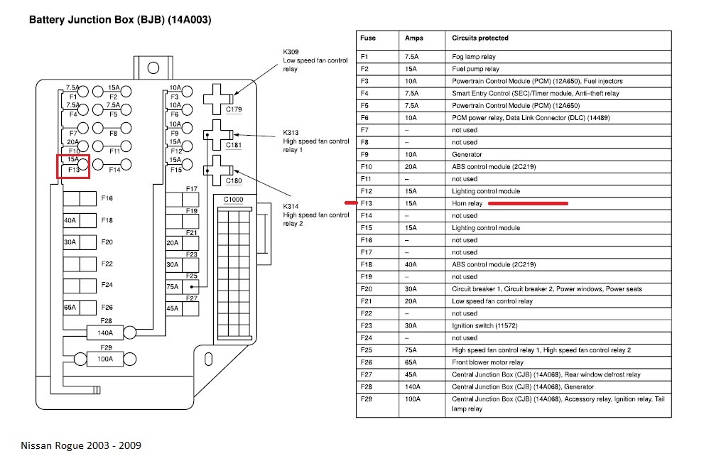
- Engine Compartment Fuse Box: Located in the engine bay, usually near the battery. This fuse box houses fuses and relays related to engine management, starting system, lighting, and other critical vehicle functions.
The diagram itself will list each fuse and relay position within these boxes. Key specifications to pay attention to include:
- Fuse Amperage (A): This is the current rating of the fuse. It's *crucial* to replace a blown fuse with one of the *exact same* amperage rating. Using a higher amperage fuse can allow excessive current to flow, potentially damaging components or causing a fire. Using a lower amperage fuse will likely cause it to blow prematurely.
- Circuit Name: This describes what the fuse protects (e.g., "Headlight (Right)," "Radio," "Power Window (Rear Left)").
- Fuse Type: Most likely MINI or ATO style fuses. The diagram may indicate the specific type used. Visually inspect a blown fuse to confirm you're purchasing the correct replacement.
- Relay Assignments: Relays are electromechanical switches that control higher-current circuits. The diagram will identify which relay controls which function (e.g., "Fuel Pump Relay," "Headlight Relay"). A relay failure can often mimic a fuse issue.
Remember to note the specific model year of your Rogue, as minor variations in fuse assignments can occur even within the same generation. Check your owner's manual first. If its missing the fuse diagram, then our downloadble diagram (mentioned at end of article) is exactly what you need!
Decoding the Symbols: Lines, Colors, and Icons
Fuse box diagrams employ a standardized set of symbols to convey information efficiently. Understanding these symbols is essential for accurate interpretation:
- Solid Lines: Indicate direct electrical connections.
- Dashed Lines: May represent connections that are only present in certain trim levels or configurations, or may represent ground connections.
- Colors: Some diagrams use color-coding to differentiate between various systems (e.g., red for ignition, blue for lighting). However, color coding is less common on fuse box diagrams than wiring diagrams.
- Icons: Standardized icons represent the type of component being protected. For example:
- A headlight icon signifies the headlight circuit.
- A speaker icon indicates the radio circuit.
- A window icon designates the power window circuit.
- A fan icon designates the A/C system.
- Ground Symbol: Often depicted as three horizontal lines decreasing in length, this indicates a connection to the vehicle's chassis ground (negative terminal of the battery). A bad ground can cause all sorts of bizarre electrical issues.
The lines show electrical pathways. Grounding is crucial; poor grounding leads to voltage drops and erratic behavior. Often a loose screw or corroded connection causes the problem.
How It Works: Basic Electrical Circuit Theory
At its core, an electrical circuit is a closed loop that allows current to flow from a power source (the battery) to a load (a component like a light bulb) and back to the power source. The fuse is a sacrificial component placed within this circuit. It's designed to break the circuit if the current exceeds its rated amperage. This protects the wiring and components from overheating and potential damage. Think of it as a circuit breaker in your house.
A blown fuse indicates that there was an overcurrent situation. This could be caused by:
- Short Circuit: A direct connection between a power wire and ground, bypassing the intended load. This causes a massive surge of current.
- Overload: Too many devices drawing power from the same circuit, exceeding the fuse's capacity.
- Component Failure: A faulty component (e.g., a motor with shorted windings) drawing excessive current.
When a fuse blows, the circuit is opened, and the component it protects stops working. Replacing the fuse restores the circuit, but only if the underlying problem is resolved. If the fuse blows again immediately after replacement, it indicates that the underlying overcurrent condition still exists.
Real-World Use: Basic Troubleshooting Tips
Here's how to use the fuse box diagram for basic troubleshooting:
- Identify the Problem: Determine which component isn't working.
- Consult the Diagram: Locate the fuse associated with that component on the fuse box diagram.
- Inspect the Fuse: Remove the fuse and visually inspect it. A blown fuse will typically have a broken filament or a darkened appearance. A multimeter can also be used to test continuity – a good fuse will have continuity (zero resistance).
- Replace the Fuse: If the fuse is blown, replace it with a new fuse of the *exact same* amperage rating.
- Test the Component: Check if the component is now working.
- If the Fuse Blows Again: This indicates a more serious problem. Do not keep replacing fuses. It's time to investigate the wiring and the component itself for shorts or other issues. Consult a qualified mechanic if you're not comfortable with electrical troubleshooting.
Before touching anything, disconnect the negative terminal of the battery. This prevents accidental shorts and potential electrical shocks. Also, always have a fuse puller handy. They are usually located inside of the fuse box. Using pliers or other tools to remove fuses can damage the fuse box.
Safety: Highlighting Risky Components
Working with automotive electrical systems involves inherent risks. Pay particular attention to these areas:
- Airbag System: Circuits related to the airbag system are extremely sensitive. Incorrect handling can trigger airbag deployment, causing serious injury. If you suspect an issue with the airbag system, consult a qualified technician. Never probe or tamper with airbag wiring unless you are specifically trained to do so.
- High-Current Circuits: Circuits powering the starter motor, alternator, and certain engine management components carry high current. Avoid shorting these circuits, as it can cause sparks, burns, and damage to the vehicle.
- Fuel System: Circuits related to the fuel pump and injectors should be treated with caution. Avoid sparks or open flames near fuel lines, as this can create a fire hazard.
- Always Disconnect the Battery: As mentioned, disconnecting the negative terminal of the battery is the single most important safety precaution.
Remember, electricity doesn't forgive mistakes. When in doubt, consult a qualified automotive electrician. It's better to be safe than sorry.
With the right knowledge and a bit of care, you can use the 2014 Nissan Rogue fuse box diagram to confidently diagnose and repair electrical problems, add aftermarket accessories, and gain a deeper understanding of your vehicle's electrical system.
We have a downloadable version of the 2014 Nissan Rogue Fuse Box Diagram available. It provides a clear and detailed visual representation of fuse locations, amperages, and circuit assignments. Download now!