2015 Nissan Altima Fuse Box Diagram
The 2015 Nissan Altima is a reliable vehicle, but like any car, electrical issues can arise. Understanding your Altima's fuse box diagram is crucial for troubleshooting and repairing electrical problems. It's also essential for safely adding aftermarket electrical components. This article provides a detailed explanation of the 2015 Nissan Altima fuse box diagram, empowering you to diagnose and fix common electrical issues. Having this knowledge allows you to save money on mechanic fees and understand the intricate workings of your car's electrical system. We've also got the complete diagram available for download – more on that later.
Purpose of the Fuse Box Diagram
The fuse box diagram is essentially a roadmap of your car's electrical system. It identifies the location of each fuse and relay, along with the specific circuit it protects. Without it, tracing a blown fuse or diagnosing a short circuit becomes a frustrating and time-consuming guessing game. The diagram serves several key purposes:
- Troubleshooting Electrical Problems: When an electrical component stops working (e.g., headlights, radio, power windows), the fuse box diagram helps you quickly identify and check the corresponding fuse.
- Safe Modification and Additions: Adding aftermarket accessories like amplifiers, lighting, or dashcams requires tapping into the car's electrical system. The diagram helps you identify suitable circuits and properly fuse your new additions to prevent damage and fire hazards.
- Understanding Your Car's Electrical System: Studying the diagram can give you a deeper understanding of how the different electrical components are connected and protected.
- Preventing Further Damage: Incorrectly replacing a fuse with a higher amperage fuse can lead to overloading the circuit and potentially cause a fire. The diagram indicates the correct amperage rating for each fuse.
Key Specs and Main Parts
The 2015 Nissan Altima has two main fuse box locations:
- Inside the Vehicle (Cabin Fuse Box): Typically located under the dashboard on the driver's side, this fuse box houses fuses for interior components like the radio, lights, power windows, and climate control.
- Under the Hood (Engine Compartment Fuse Box): Located in the engine bay, this fuse box contains fuses for engine management systems, headlights, horn, and other critical components. This is a more rugged environment for components, and they are typically rated for a wider temperature range.
Key Components:
- Fuses: These are sacrificial devices designed to protect electrical circuits from overcurrent. They contain a thin wire that melts and breaks the circuit when the current exceeds a specified level. Fuses are rated in Amps (A), which indicates the maximum current they can handle.
- Relays: Relays are electrically operated switches that control high-current circuits using a low-current signal. They allow the car's computer or a switch to control devices like the starter motor, headlights, and fuel pump. They consist of a coil, an armature, and contacts.
- Circuit Breakers: Unlike fuses, circuit breakers can be reset after tripping. They protect circuits from overcurrent by interrupting the flow of electricity. While less common than fuses in this particular model year, understanding their function is still important.
- Fuse Puller: Usually located inside one of the fuse boxes, this small plastic tool is used to safely remove fuses.
Symbols: Lines, Colors, and Icons
Understanding the symbols on the fuse box diagram is essential for correct interpretation. Here's a breakdown of common symbols:
- Lines: Solid lines represent the electrical wires connecting the components. Dashed lines may indicate a ground connection. Different line weights might also indicate the gauge (thickness) of the wire. Thicker wires are generally used for higher-current circuits.
- Colors: Wire colors are often indicated on the diagram. These colors correspond to the actual wire colors in the car. This helps you trace circuits and identify specific wires. Common colors include red (power), black (ground), blue, green, yellow, and white.
- Icons: Icons represent the different electrical components. Common icons include:
- Light Bulb: Represents lights (headlights, taillights, interior lights).
- Resistor: A zig-zag line representing a component that restricts current flow.
- Motor: A circle with an "M" inside, representing an electric motor (power windows, wipers).
- Speaker: Represents the audio speakers.
- Battery: Represents the car battery.
- Switch: Represents a manual or electronic switch.
- Relay: A square with the relay symbol inside.
- Fuse: Typically represented by a stylized "S" shape or a rectangle with a break in the middle.
The fuse box diagram will typically provide a legend explaining the meaning of each symbol used. The absence of standardization across all vehicle manufacturers means understanding the legend is vital.
How It Works
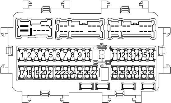
The fuse box diagram is organized to show the electrical distribution within the vehicle. Each fuse and relay is assigned a specific location number. The diagram lists each location number and the corresponding circuit it protects. For example, the diagram might indicate that fuse number 10 in the cabin fuse box protects the radio. If your radio stops working, you would locate fuse number 10 in the cabin fuse box and check its condition.
The electrical system works by providing a complete circuit for electricity to flow from the battery, through the component, and back to the battery. Fuses are placed in this circuit as a weak link. If there is a surge of current (e.g., due to a short circuit), the fuse will blow, interrupting the circuit and preventing damage to the component and the wiring. Relays act as remote-controlled switches, allowing low-current signals to control high-current devices. This is essential for components that require a lot of power, such as the starter motor.
Real-World Use: Basic Troubleshooting Tips
Here are some basic troubleshooting tips using the fuse box diagram:
- Identify the Problem: Determine which electrical component is not working.
- Locate the Corresponding Fuse: Consult the fuse box diagram to identify the fuse associated with the non-functional component. Note both the fuse location and amperage.
- Inspect the Fuse: Use a fuse puller to remove the fuse. Visually inspect it for a broken filament. If the filament is broken, the fuse is blown. A multimeter can also be used to test the fuse for continuity.
- Replace the Fuse: Replace the blown fuse with a new fuse of the same amperage rating. Never use a fuse with a higher amperage rating, as this can damage the circuit.
- Test the Component: After replacing the fuse, test the component to see if it is working. If the fuse blows again immediately, there is likely a short circuit in the wiring or the component itself. Further diagnosis is required.
- Consult a Professional: If you are unsure about any aspect of the troubleshooting process, consult a qualified mechanic.
Safety Considerations
Working with automotive electrical systems can be dangerous. Here are some important safety precautions:
- Disconnect the Battery: Before working on any electrical component, disconnect the negative (-) terminal of the car battery. This will prevent accidental shocks and short circuits.
- Use the Correct Tools: Use insulated tools to avoid electrical shocks.
- Never Replace a Fuse with a Higher Amperage Fuse: This can overload the circuit and cause a fire.
- Be Careful Around Airbags: Airbags are electronically controlled and can deploy unexpectedly if mishandled. Consult a professional if you need to work near airbag components. Improper handling of the airbag system can result in serious injury.
- Be Mindful of High-Current Circuits: The starter motor and alternator circuits carry high currents and can be dangerous. Exercise extreme caution when working near these components.
- Consult a Professional if Needed: If you are unsure about any aspect of the repair process, consult a qualified mechanic.
Especially risky are the circuits related to the airbags and the Engine Control Module (ECM). Tampering with these without proper knowledge can lead to serious consequences. For instance, the ECM controls critical engine functions, and any disruption can cause the vehicle to stall or operate erratically.
We have the complete 2015 Nissan Altima fuse box diagram available for download. This digital copy will be a valuable resource for your troubleshooting and repair efforts. Contact us [provide contact info here] to get the download link!