2013 Nissan Altima Fuse Box Diagram
The 2013 Nissan Altima fuse box diagram is an indispensable tool for any DIY mechanic, experienced car owner, or modification enthusiast. Whether you're tackling electrical repairs, adding aftermarket accessories, or simply trying to understand your vehicle's electrical system, this diagram provides a roadmap to navigate the complex network of fuses, relays, and circuits that keep your Altima running smoothly. This article will break down the diagram, explaining its key elements and how to use it effectively. And yes, we have the full 2013 Nissan Altima fuse box diagram available for download; you'll find the download link at the end.
Purpose of the Fuse Box Diagram
The fuse box diagram serves several critical purposes:
- Electrical Troubleshooting: When an electrical component fails (e.g., a headlight, the radio, or the power windows), the first step is often to check the corresponding fuse. The diagram identifies which fuse protects that particular circuit.
- Safe Modification: Adding aftermarket accessories (e.g., a new sound system, auxiliary lighting) requires tapping into the Altima's electrical system. The diagram allows you to identify suitable circuits and choose appropriate fuse ratings to avoid overloading the system and causing damage.
- Understanding Vehicle Systems: The diagram provides a visual representation of how different electrical systems are interconnected, improving your overall understanding of the vehicle's operation.
- Preventing Electrical Fires: Identifying and replacing blown fuses with the correct amperage rating is crucial for preventing electrical fires. An improperly rated fuse can allow excessive current to flow, overheating the wiring and potentially causing a fire.
Key Specs and Main Parts
The 2013 Nissan Altima actually has multiple fuse boxes. The most important ones are typically located:
- Inside the cabin, under the dashboard: This is the primary fuse box, usually located on the driver's side, near the steering column. It houses fuses for interior lights, radio, power windows, and other comfort and convenience features.
- In the engine compartment: This fuse box is typically located near the battery and contains fuses for engine-related components, such as the fuel pump, ignition system, and cooling fan. It also often contains fuses for the headlights and other exterior lighting.
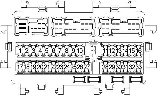
The diagram will show each fuse box separately, often with a grid layout corresponding to the physical arrangement of the fuses. Each fuse location will be labeled with a number or letter, and the diagram will provide a key that identifies the circuit protected by that fuse and its amperage rating.
Key Components:
- Fuses: These are the sacrificial components that protect circuits from overcurrent. They contain a thin wire or strip that melts and breaks the circuit when the current exceeds a specified limit. The amperage rating (e.g., 5A, 10A, 15A, 20A) indicates the maximum current the fuse can handle before blowing.
- Relays: Relays are electromagnetic switches that allow a low-current circuit to control a high-current circuit. They are used to switch on devices that require a lot of power, such as the starter motor, headlights, and air conditioning compressor. The diagram will show the location of relays and their corresponding functions.
- Circuit Breakers: Some circuits, especially those related to the power windows and seats, may be protected by circuit breakers instead of fuses. Circuit breakers automatically reset themselves after a short period of time, allowing the circuit to function again once the overload is removed. However, repeated tripping of a circuit breaker indicates a problem that needs to be addressed.
Understanding Fuse Box Diagram Symbols
Understanding the symbols used in the diagram is crucial for accurate interpretation:
- Lines: Lines represent electrical wiring. Thicker lines might indicate a heavier gauge wire, capable of carrying more current. Dotted lines may indicate ground connections or specialized wiring.
- Colors: Wire colors are typically indicated on the diagram (e.g., blue, red, black). These colors correspond to the actual wire colors in the vehicle's wiring harness and can be helpful for tracing circuits. However, wire colors can vary depending on the specific vehicle trim level and production date, so always double-check the diagram against the actual wiring in your vehicle.
- Icons/Symbols: Standardized symbols are used to represent different components, such as fuses, relays, switches, and loads (e.g., headlights, motors). Refer to the diagram's legend for a complete list of symbols and their meanings. A common symbol is a zig-zag line representing a resistor (like the internal element of a fuse) or a box with a wavy line representing a relay coil.
- Amperage Rating: The amperage rating of each fuse is usually indicated numerically (e.g., 10A, 20A) next to the fuse location on the diagram.
How It Works: Following a Circuit
The fuse box diagram allows you to trace a circuit from its power source (typically the battery) through the fuse, the switch (if any), the wiring, and the load (the device being powered). This can be helpful for diagnosing electrical problems. For example, if a headlight is not working, you can use the diagram to identify the fuse that protects the headlight circuit. If the fuse is blown, replacing it may solve the problem. If the fuse is not blown, you can use the diagram to trace the circuit to the headlight switch and then to the headlight itself, checking for broken wires or faulty connections along the way.
The fuse serves as a critical protective device. If there's a short circuit (where a wire accidentally connects directly to ground), or if a component draws too much current, the fuse blows, cutting off the power and preventing damage to the wiring and other components.
Real-World Use: Basic Troubleshooting Tips
- Identify the Problem: Determine which electrical component is not working.
- Consult the Diagram: Locate the appropriate fuse box diagram for your 2013 Nissan Altima. Confirm it is for your specific trim level if possible, as minor variations can exist.
- Locate the Fuse: Identify the fuse that protects the circuit for the non-working component.
- Inspect the Fuse: Visually inspect the fuse. A blown fuse will have a broken filament or a darkened appearance. If you are unsure, use a multimeter to test the fuse for continuity. A good fuse will have continuity (a reading of 0 ohms or a beep on the multimeter).
- Replace the Fuse: If the fuse is blown, replace it with a new fuse of the exact same amperage rating. Using a fuse with a higher amperage rating can damage the wiring and potentially cause a fire.
- Test the System: After replacing the fuse, test the electrical component to see if it is now working. If the fuse blows again immediately, there is likely a short circuit or other problem in the circuit that needs to be investigated further.
- Document Everything: Keep a record of the fuses you've replaced and any problems you've encountered. This will help you troubleshoot future electrical issues more efficiently.
Safety Considerations
Working with automotive electrical systems can be dangerous. Observe the following safety precautions:
- Disconnect the Battery: Before working on any electrical components, disconnect the negative terminal of the battery to prevent accidental short circuits.
- Avoid Water: Never work on electrical systems in wet conditions.
- Use Insulated Tools: Use insulated tools to prevent electric shock.
- Replace Fuses Correctly: Always replace blown fuses with fuses of the correct amperage rating. Never use a fuse with a higher amperage rating.
- Be Careful with Airbags: Some fuse circuits are related to the airbag system. Mishandling these circuits can cause the airbags to deploy accidentally, which can be very dangerous. If you are unsure about working on airbag-related circuits, consult a qualified technician.
- The fuel pump circuit is also something to be careful around, as improper handling can lead to fuel leaks or other hazards.
Always remember that dealing with automotive electrical systems requires a degree of caution and understanding. If you're uncomfortable with any aspect of the process, it's best to consult a qualified mechanic.
Ready to get started? You can download the complete 2013 Nissan Altima fuse box diagram here.