02 Lincoln Town Car Fuse Box Diagram
Alright, let's dive into the fuse box diagram for your 2002 Lincoln Town Car. Understanding this diagram is absolutely crucial whether you're tackling a minor electrical glitch, planning some custom modifications, or just want to deepen your understanding of your vehicle's systems. Think of it as the roadmap to your car's electrical nervous system. We have the complete diagram ready for you to download at the end of this article, so you'll have it handy when you need it.
Purpose of the Fuse Box Diagram
Why bother with a fuse box diagram? The simple answer is diagnostics and repair. When an electrical component stops working – headlights, radio, power windows, you name it – the first place a seasoned mechanic (or a smart DIYer) will look is the fuse box. A blown fuse is a protective measure, indicating an overload or short circuit. The diagram allows you to quickly identify the fuse associated with the malfunctioning component. Without it, you're essentially guessing, pulling fuses at random, which is time-consuming and potentially damaging.
Beyond repairs, the diagram is invaluable for electrical modifications. Planning to add aftermarket lights, a sound system, or any other electrical accessory? Knowing which circuits are available and their current ratings is essential for safe and reliable installation. Overloading a circuit can lead to blown fuses, damaged wiring, and even fires. The diagram provides the information you need to avoid these pitfalls.
Key Specs and Main Parts of the Fuse Box System
The 2002 Lincoln Town Car typically has two main fuse box locations:
- Under the Hood (Power Distribution Box): Located in the engine compartment, this box houses fuses and relays for high-current systems like the starter, alternator, headlights, and cooling fan. It acts as the primary power distribution center.
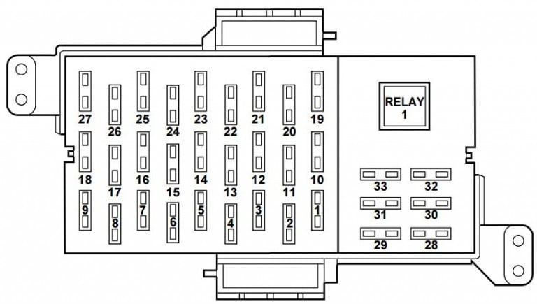
- Under the Dashboard (Central Junction Box): Usually found under the dashboard on the driver's side, this box handles lower-current circuits like the radio, interior lights, power windows, and instrument panel.
Each fuse box contains:
- Fuses: These are the sacrificial links in the electrical circuits. They contain a thin wire that melts and breaks the circuit when excessive current flows through it, preventing damage to other components. Fuses are rated in amperes (amps), indicating the maximum current they can handle.
- Relays: Electrically operated switches that allow a low-current circuit to control a high-current circuit. They're often used for components that require a lot of power, like the headlights and starter.
- Circuit Breakers: Similar to fuses, but they can be reset after tripping. They're typically used for systems that might experience temporary overloads, like power windows.
- Connectors: These are the points where wires connect to the fuse box. They're designed to provide a secure and reliable electrical connection.
Understanding the Symbols in the Fuse Box Diagram
The fuse box diagram uses a standardized set of symbols and conventions to represent the different components and their connections. Learning to interpret these symbols is crucial for understanding the diagram.
- Lines: Solid lines represent wires. Different colors may be used to indicate different wire gauges or functions (e.g., red for power, black for ground). The diagram we offer for download has the color codes detailed.
- Fuse Symbol: Typically a stylized "S" shape enclosed in a rectangle. The amperage rating of the fuse is usually indicated next to the symbol.
- Relay Symbol: A rectangle with a coil symbol inside, representing the relay's electromagnet. A switch symbol next to the coil indicates the contacts that are opened or closed by the relay.
- Connector Symbol: Often represented by a circle or rectangle with lines radiating outward, indicating the connection points for wires.
- Ground Symbol: A series of horizontal lines decreasing in size, indicating a connection to the vehicle's chassis, which serves as the electrical ground.
The diagram also typically includes a legend or key that explains the meaning of each symbol and color code used.
How the Fuse Box System Works
The fuse box system works by providing a centralized point for distributing electrical power to various components throughout the vehicle. Power from the battery flows through the main power distribution box under the hood, which then branches out to other systems via fuses, relays, and circuit breakers.
Each circuit is protected by a fuse of the appropriate amperage rating. If a short circuit or overload occurs, the fuse blows, interrupting the flow of current and preventing damage to the circuit and its associated components. Relays allow low-current circuits (like the switch in the dashboard) to control high-current circuits (like the headlights). This is important because using a small switch to directly control a high-current circuit could damage the switch and create a fire hazard.
Real-World Use: Basic Troubleshooting Tips
Here's a basic troubleshooting scenario: Your radio stops working.
- Consult the Fuse Box Diagram: Locate the fuse associated with the radio in the appropriate fuse box (likely the one under the dashboard).
- Inspect the Fuse: Visually inspect the fuse. If the wire inside is broken or blackened, the fuse is blown.
- Replace the Fuse: Replace the blown fuse with a new fuse of the exact same amperage rating. Do not use a higher amperage fuse; this can damage the circuit.
- Test the Radio: Turn on the radio to see if it works. If it does, you've solved the problem.
- If the Fuse Blows Again: If the new fuse blows immediately, there's a short circuit in the radio's wiring. This requires further investigation and may involve tracing wires, checking for damaged insulation, and possibly replacing faulty components. Consult a professional if you're not comfortable with this level of troubleshooting.
Safety Considerations
Working with automotive electrical systems can be dangerous. Always disconnect the negative battery cable before working on the fuse box or any other electrical component. This prevents accidental shorts and electric shocks. Some components, such as the airbag system, store a significant amount of electrical energy and can be triggered unexpectedly if not handled properly. Do not attempt to repair or modify these systems unless you are properly trained and equipped.
Be especially cautious when working around the high-current circuits in the power distribution box under the hood. These circuits can deliver a significant electric shock. Always use insulated tools and wear appropriate safety gear. Identify the starter solenoid and alternator circuits on the diagram, as these are high risk points. Also, be careful when removing and replacing relays, ensure the ignition switch is OFF.
Finally, remember to use the correct amperage rating for fuses. Using a fuse with a higher rating can overload the circuit and cause a fire.
Download the 2002 Lincoln Town Car Fuse Box Diagram
We've compiled a comprehensive fuse box diagram for your 2002 Lincoln Town Car, covering both the under-hood and under-dash fuse boxes. This diagram includes detailed layouts, fuse amperage ratings, and component identifications. Download it here to have it readily available for your future repairs and modifications. Good luck!