02 Nissan Altima Fuse Box Diagram
Let's dive into the electrical heart of your 2002 Nissan Altima: the fuse box. This isn't just a collection of colored plastic; it's the protective network for your car's vital systems. Understanding its layout, function, and how to interpret its diagram is crucial for DIY repairs, modifications, and even basic troubleshooting. This guide will arm you with the knowledge to confidently navigate your Altima's fuse system.
Why Understanding the Fuse Box Matters
The fuse box diagram is more than just a schematic; it's your roadmap to diagnosing and resolving electrical issues. Whether you're experiencing a malfunctioning power window, a dead tail light, or a non-starting engine, the fuse box is often the first place to investigate. A blown fuse acts like a miniature circuit breaker, protecting sensitive components from damaging current overloads. Without a clear understanding of the fuse box diagram, you're essentially troubleshooting blindfolded, risking further damage or misdiagnosis.
Furthermore, for those of you into car modification or adding aftermarket accessories (like upgraded sound systems, lighting, or security systems), the fuse box becomes a crucial point for tapping into power and ensuring your additions are properly protected. A well-understood fuse box enables safe and reliable integration of these enhancements.
Key Specs and Main Parts
The 2002 Nissan Altima generally has two primary fuse box locations: one inside the passenger compartment (usually under the dashboard, near the driver's side) and another in the engine compartment, typically near the battery. Each location serves a different purpose and protects different circuits.
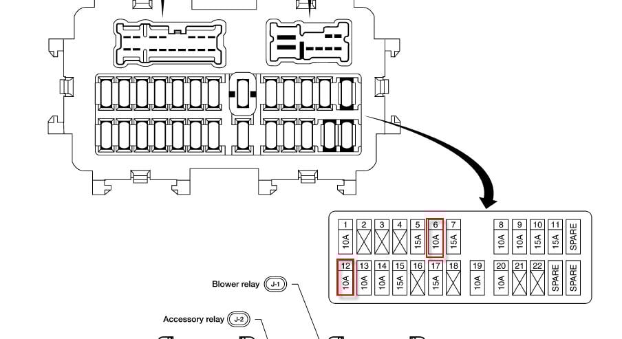
Passenger Compartment Fuse Box:
- Location: Typically under the dashboard, often accessible by removing a small panel.
- Purpose: Protects interior circuits like the radio, power windows, interior lights, and various control modules.
- Fuse Types: Primarily blade-type fuses (ATO/ATC). These are small, rectangular fuses with two exposed metal terminals.
Engine Compartment Fuse Box:
- Location: Usually near the battery, often a black plastic box with a secure lid.
- Purpose: Protects engine-related circuits such as the fuel pump, ignition system, cooling fan, and headlights.
- Fuse Types: Contains both blade-type fuses (ATO/ATC) and potentially larger, high-amperage cartridge fuses (also known as Maxi fuses or PAL fuses) for critical components. You may also find relays in this box.
Key Specs to Note: Each fuse is rated for a specific amperage (measured in amps, or A). This rating indicates the maximum current that the fuse can handle before blowing. Using a fuse with a higher amperage than specified can bypass the circuit protection and lead to serious damage or even a fire. Always replace a blown fuse with one of the same amperage.
The fuse box diagram itself is typically located on the inside of the fuse box lid. If it's missing or damaged, you can often find it online in your owner's manual or through reputable automotive repair websites (like this one!). We have a digital version for you to download; more on that later.
Decoding the Symbols: Lines, Colors, and Icons
The fuse box diagram uses a system of symbols and abbreviations to identify each fuse and its corresponding circuit. Here's a breakdown of common elements:
- Lines: Lines represent the electrical circuits. They connect the fuse symbol to the component it protects.
- Colors: While not always present, color coding on the diagram can indicate wire color in the actual wiring harness. This can be helpful for tracing circuits.
- Icons: Icons represent the component or system protected by the fuse. Common icons include:
- A light bulb icon: Represents headlights, tail lights, or interior lights.
- A radio icon: Represents the radio or audio system.
- A fan icon: Represents the cooling fan or blower motor.
- A window icon: Represents power windows.
- An ignition key icon: Represents the ignition system.
- Abbreviations: Common abbreviations include:
- ACC: Accessory power.
- IGN: Ignition power.
- ECU: Engine Control Unit.
- ABS: Anti-lock Braking System.
- Amperage Rating: Crucially, each fuse location will be labeled with the amperage rating of the fuse that should be installed there (e.g., "10A," "15A," "20A").
The diagram usually provides a layout of the fuses, correlating the physical location of each fuse with its symbol, function, and amperage rating. Take your time to familiarize yourself with these symbols; they are the key to understanding the diagram.
How It Works: The Fuse's Role in Circuit Protection
Think of a fuse as a sacrificial element in an electrical circuit. It's designed to be the weakest point, intentionally breaking the circuit if the current exceeds its rated amperage. This prevents excessive current from reaching and damaging more expensive and critical components. When a circuit experiences an overload (e.g., due to a short circuit or a malfunctioning component drawing too much power), the thin wire inside the fuse heats up and melts, interrupting the flow of electricity. This "blowing" of the fuse protects the rest of the circuit.
The amperage rating of a fuse is crucial. Using a fuse with a lower amperage than specified will cause it to blow prematurely, leading to annoying intermittent problems. Using a fuse with a higher amperage, as mentioned earlier, is extremely dangerous because it defeats the purpose of circuit protection and can lead to component damage, overheating, or even a fire.
Real-World Use: Basic Troubleshooting Tips
Here's a basic troubleshooting workflow using the fuse box diagram:
- Identify the Problem: What system is malfunctioning? Be specific (e.g., "The passenger side power window doesn't work").
- Consult the Diagram: Locate the fuse associated with the malfunctioning system in the fuse box diagram. Both fuse box locations need to be considered.
- Inspect the Fuse: Physically check the fuse. Look for a broken or melted filament inside the fuse. A blown fuse will have a visible break.
- Test the Fuse: For a more accurate diagnosis, use a multimeter set to continuity mode (or resistance mode). Touch the probes to the two terminals of the fuse. A good fuse will show continuity (a near-zero resistance reading). A blown fuse will show no continuity (infinite resistance).
- Replace the Fuse: If the fuse is blown, replace it with a fuse of the same amperage rating.
- Test the System: After replacing the fuse, test the system to see if the problem is resolved.
- If the Fuse Blows Again: If the new fuse blows immediately or shortly after replacement, it indicates a deeper underlying issue in the circuit. This could be a short circuit, a wiring problem, or a malfunctioning component. Further diagnosis by a qualified mechanic is recommended. Do not simply keep replacing the fuse with progressively higher amperage fuses!
Safety First: Identifying Risky Components
Working with electrical systems involves inherent risks. Here are a few safety precautions to keep in mind:
- Disconnect the Battery: Before working on the fuse box, especially the engine compartment fuse box, it's always a good idea to disconnect the negative (-) terminal of the battery to prevent accidental shorts.
- Identify High-Amperage Fuses and Relays: Pay close attention to the high-amperage fuses and relays in the engine compartment fuse box. These control critical systems like the fuel pump and ignition, and improper handling can be dangerous.
- Avoid Touching Exposed Wires: Never touch exposed wires, especially when the ignition is on.
- Use Proper Tools: Use insulated tools when working on electrical systems.
- Don't Modify Fuses: Never attempt to repair a blown fuse or bypass it with a piece of wire. This is extremely dangerous and can lead to serious damage or fire.
- Be Aware of Airbag Circuits: Some fuses may be related to the airbag system. Consult your repair manual, and if you are not comfortable working around the airbag system, seek professional assistance. Improper handling can cause accidental airbag deployment.
Important Note: If you are unsure about any aspect of electrical troubleshooting, it's always best to consult a qualified mechanic. Electrical systems can be complex, and improper repairs can be dangerous and costly.
You now have a solid understanding of your 2002 Nissan Altima's fuse box and how to use its diagram for troubleshooting and repairs. To help you even further, we've got a downloadable version of the 2002 Nissan Altima Fuse Box Diagram available. Use it wisely, and stay safe!