03 Mustang 2003 Ford Mustang Fuse Box Diagram
The 2003 Ford Mustang, a member of the SN-95 generation, is a popular platform for customization and maintenance. A crucial component for diagnosing electrical issues and undertaking any modifications is the fuse box diagram. This article serves as a comprehensive guide to understanding the '03 Mustang fuse box, enabling you to confidently troubleshoot electrical problems and perform upgrades.
Purpose of the Fuse Box Diagram
The fuse box diagram is essentially a roadmap to your Mustang's electrical system. Its purpose is multifaceted:
- Troubleshooting Electrical Problems: When a circuit fails (lights don’t work, radio is dead, etc.), the diagram helps you quickly identify and inspect the corresponding fuse.
- Identifying Circuits: Understanding which fuse protects which component allows for targeted diagnostics. You don't have to guess which fuse controls the power windows, for instance.
- Planning Modifications: If you're adding aftermarket accessories (performance lighting, audio systems, etc.), the diagram lets you find suitable circuits to tap into, ensuring proper power distribution and circuit protection.
- Preventing Damage: By understanding the amperage ratings of fuses, you can avoid overloading circuits, which could lead to blown fuses, damaged wiring, or even electrical fires.
- General Understanding: Familiarity with the fuse box diagram enhances your overall understanding of your Mustang's electrical architecture.
Without this diagram, you're essentially working blind, increasing the risk of misdiagnosis and potential damage.
Key Specs and Main Parts
The '03 Mustang actually has two primary fuse locations:
- Interior Fuse Box: Located under the driver's side dashboard, near the parking brake release. This box primarily contains fuses for interior components like lights, the radio, power windows, and the instrument cluster.
- Engine Compartment Fuse Box (Power Distribution Box): Situated in the engine bay, typically on the driver's side near the battery. This box houses fuses and relays that protect high-current circuits like the engine control unit (ECU), fuel pump, starter motor, and headlights.
Both fuse boxes contain several key components:
- Fuses: These are sacrificial devices designed to protect circuits from overcurrent. They consist of a thin wire that melts and breaks the circuit when the current exceeds its rated amperage. Common fuse types include blade fuses (ATO/ATC) and Maxi-fuses (high amperage).
- Relays: Electrically operated switches that allow a low-current circuit to control a high-current circuit. Relays are used for components that require significant power, like the fuel pump or air conditioning compressor.
- Circuit Breakers: Similar to fuses, but they can be reset after tripping. Circuit breakers are often used for circuits that experience frequent overloads, such as power seats.
- The Fuse Box Housing: Provides physical protection for the fuses, relays, and circuit breakers, and usually has a diagram indicating the function of each component.
Understanding the physical location and the purpose of each component within these boxes is paramount before attempting any electrical work.
Understanding the Symbols
The fuse box diagram employs a variety of symbols to represent different components and their functions. These symbols might seem cryptic at first, but they are standardized and relatively easy to decipher once you understand the basic principles.
- Lines: Solid lines represent electrical wires connecting components. Dashed lines often indicate ground connections.
- Fuse Symbols: Fuses are typically represented by a zig-zag line within a rectangle. The amperage rating is usually indicated next to the symbol (e.g., "20A").
- Relay Symbols: Relays are depicted as a coil symbol connected to a switch. The coil represents the electromagnet that activates the switch, while the switch symbol shows the contacts that are opened or closed when the relay is energized.
- Component Symbols: Specific components, like headlights, motors, and sensors, have their own unique symbols. Refer to a legend on the diagram (if available) or consult online resources to identify these symbols.
- Color Coding: While not always present *directly* on the diagram, the wiring associated with specific fuses might be color-coded within the vehicle itself. It's crucial to consult a wiring diagram (separate from the fuse box diagram) for color-coding information.
Note that a crucial skill is understanding context. A motor symbol near a fuse labeled "WIPER" likely indicates the windshield wiper motor circuit.
How It Works: The Circuit Protection Principle
The fuse box works on a simple yet effective principle: circuit protection. Each fuse is designed to protect a specific circuit from excessive current. Here's how it works:
- Normal Operation: Under normal operating conditions, current flows through the circuit, including the fuse, without any issues. The fuse's wire remains intact.
- Overcurrent Event: If a short circuit occurs (e.g., a wire chafes and makes contact with the chassis), or if a component draws excessive current (e.g., a faulty motor), the current in the circuit rapidly increases.
- Fuse Blows: The excessive current heats up the fuse's wire until it melts, breaking the circuit and stopping the flow of current.
- Circuit Protection: By breaking the circuit, the fuse prevents damage to the wiring, components, and potentially the vehicle itself.
It's important to remember that a blown fuse is a symptom, not the cause. Replacing a blown fuse without addressing the underlying issue will likely result in the fuse blowing again.
Real-World Use: Basic Troubleshooting Tips
Here's a step-by-step guide to using the fuse box diagram for basic troubleshooting:
- Identify the Problem: Determine which component is not working.
- Consult the Diagram: Locate the fuse in the appropriate fuse box that corresponds to the malfunctioning component.
- Inspect the Fuse: Remove the fuse using a fuse puller (usually found in the fuse box). Visually inspect the fuse. If the wire inside is broken, the fuse is blown. A multimeter set to continuity can also be used to test the fuse.
- Replace the Fuse: Replace the blown fuse with a new fuse of the same amperage rating. Using a fuse with a higher amperage rating can overload the circuit and cause serious damage.
- Test the Component: After replacing the fuse, test the component to see if it is now working.
- If the Fuse Blows Again: If the new fuse immediately blows again, there is a short circuit or other problem in the circuit that needs to be investigated by a qualified mechanic. Do not continue replacing fuses without diagnosing the underlying issue.
For example, if your headlights are not working, consult the diagram to find the headlight fuse (or relay). Check the fuse. If it's blown, replace it. If the new fuse blows immediately, you likely have a short in the headlight wiring.
Safety Considerations
Working with electrical systems can be dangerous. Always take the following precautions:
- Disconnect the Battery: Before working on any electrical component, disconnect the negative terminal of the battery to prevent accidental shocks or short circuits.
- Use Proper Tools: Use insulated tools designed for electrical work.
- Avoid Water: Never work on electrical systems in wet conditions.
- Identify Risky Components: Be especially careful when working with high-voltage components like the ignition system and the ECU. These components can deliver a dangerous electrical shock.
- Never Bypass a Fuse: Never bypass a fuse with a wire or other conductive material. This eliminates the circuit protection and can lead to serious damage or fire.
Disclaimer: Working on automotive electrical systems can be hazardous. If you are not comfortable performing these tasks, consult a qualified mechanic.
Download the Diagram
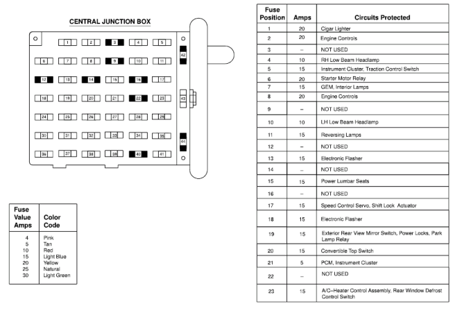
To aid you in your troubleshooting and maintenance efforts, we have a high-resolution, printable PDF version of the 2003 Ford Mustang fuse box diagram readily available. It includes both the interior and engine compartment fuse box layouts, complete with component designations and amperage ratings. This diagram is an invaluable resource for any '03 Mustang owner.
You can download the diagram here: [Insert Download Link Here - Replace with the actual link]
By understanding and utilizing this diagram, you can confidently tackle a wide range of electrical issues on your 2003 Ford Mustang.