03 Nissan Altima Fuse Box Diagram
Let's dive into the fuse box diagram of a 2003 Nissan Altima. Understanding this diagram is crucial for any intermediate car owner, modder, or DIY mechanic. Whether you're tackling electrical repairs, adding aftermarket accessories, or simply trying to understand your vehicle's electrical system, this guide will provide you with the knowledge you need. Having access to this diagram can save you time, money, and frustration.
Purpose of the Fuse Box Diagram
The fuse box diagram is essentially a roadmap for your car's electrical system. It identifies each fuse, its amperage rating, and the circuit it protects. This is invaluable for several reasons:
- Troubleshooting electrical issues: When something electrical malfunctions (e.g., a light stops working, the radio cuts out), the first step is often to check the corresponding fuse. The diagram tells you exactly which fuse to inspect.
- Adding aftermarket accessories: When installing new components like amplifiers, lights, or alarms, you need to tap into the electrical system. The diagram helps you identify appropriate circuits and fuse sizes to avoid overloading and damaging the system.
- General understanding of the vehicle's electrical system: Studying the diagram helps you learn how different components are interconnected and how the electrical system as a whole functions.
Key Specs and Main Parts of a 2003 Nissan Altima Fuse Box
The 2003 Nissan Altima typically has two main fuse box locations:
- Inside the passenger compartment: Usually located on the driver's side, near the lower dashboard. This fuse box primarily protects circuits related to interior components, such as lights, radio, and power windows.
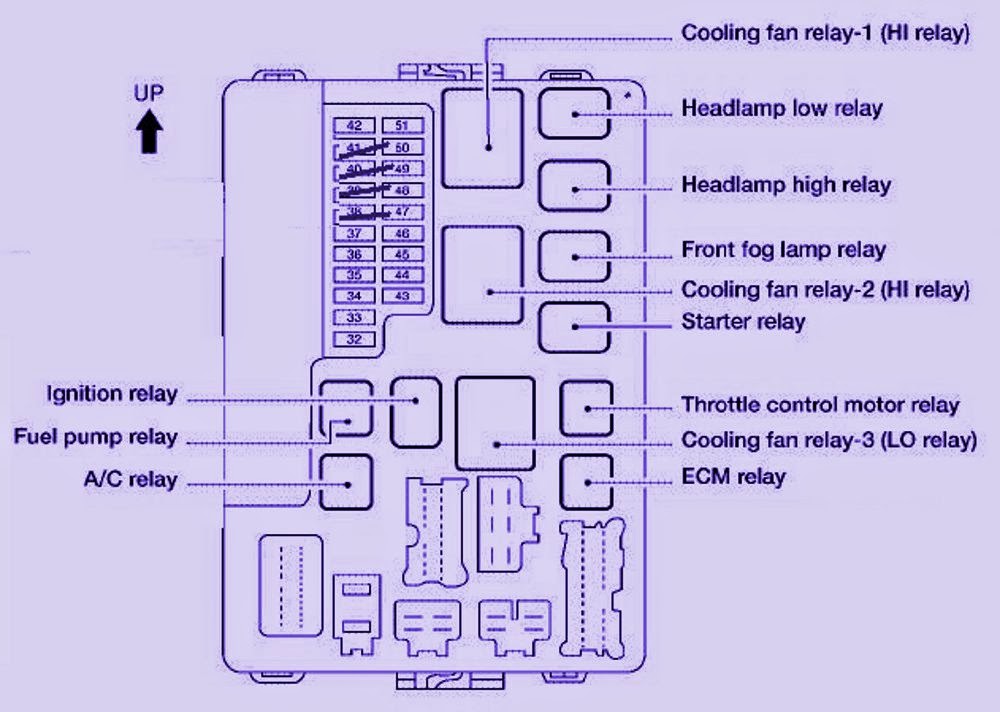
- Under the hood: Located in the engine compartment, often near the battery. This fuse box houses fuses and relays for critical engine management systems, exterior lights, and other high-current components.
Within each fuse box, you'll find the following key components:
- Fuses: These are small, inexpensive safety devices designed to protect electrical circuits from overcurrent. Each fuse has a specific amperage rating (e.g., 5A, 10A, 15A) indicated on the fuse itself and on the diagram. Amperage is the measure of electrical current.
- Relays: These are electromechanical switches that control high-current circuits using a low-current signal. Relays are often used for components like headlights, the starter motor, and the fuel pump.
- Fuse puller: Usually a small plastic tool included in the fuse box to safely remove fuses without damaging them.
- Fuse box cover: The cover protects the fuses and usually has a diagram printed on it or a label attached showing the fuse layout.
Decoding Fuse Box Symbols and Diagram Conventions
Fuse box diagrams use standardized symbols and conventions to represent different components and circuits. Understanding these symbols is crucial for interpreting the diagram correctly.
- Lines: Lines on the diagram represent electrical wires connecting different components. Thicker lines may indicate higher-current circuits.
- Colors: Wire colors are often indicated on the diagram (e.g., "Red," "Blue/White"). This is helpful for tracing wires in the vehicle.
- Fuse Symbols: Fuses are typically represented by a rectangle with a wavy line inside.
- Relay Symbols: Relays are usually depicted as a coil and a switch. The coil represents the electromagnet that controls the switch.
- Component Icons: Each fuse is labeled with an icon or abbreviation indicating the component it protects (e.g., "HEAD," "FUEL PUMP," "A/C").
Pay close attention to the amperage rating of each fuse. Replacing a blown fuse with one of a higher amperage can be extremely dangerous, as it can overload the circuit and potentially cause a fire.
How the Fuse Box Works
The fuse box acts as a central distribution point for electrical power in your vehicle. Power from the battery flows through the main power cables to the fuse boxes. From there, it's distributed to individual circuits through fuses and relays.
Each fuse protects a specific circuit by interrupting the flow of current if it exceeds the fuse's amperage rating. When an overcurrent occurs (e.g., due to a short circuit or a component failure), the thin wire inside the fuse melts, breaking the circuit and preventing damage to other components.
Relays allow low-current circuits (e.g., the headlight switch) to control high-current circuits (e.g., the headlights). When the low-current circuit is activated, the relay coil energizes, closing the switch and allowing current to flow to the high-current component.
Real-World Use: Basic Troubleshooting with the Fuse Box Diagram
Let's say your 2003 Altima's radio suddenly stops working. Here's how you can use the fuse box diagram to troubleshoot the issue:
- Consult the diagram: Locate the fuse box diagram (usually on the fuse box cover or in the owner's manual – we have a downloadable copy, see bottom). Identify the fuse labeled "RADIO" or something similar. Note its amperage rating.
- Locate the fuse: Open the relevant fuse box (likely the one inside the passenger compartment) and find the fuse corresponding to the radio.
- Inspect the fuse: Visually inspect the fuse. If the wire inside the fuse is broken or blackened, the fuse is blown.
- Replace the fuse: Use the fuse puller to remove the blown fuse and replace it with a new fuse of the same amperage rating.
- Test the radio: Turn on the radio to see if it now works. If it does, the problem was a blown fuse. If it doesn't, there may be a more serious issue with the radio or its wiring.
Important Troubleshooting Tips:
- Always replace a blown fuse with one of the same amperage rating. Using a higher amperage fuse can damage the circuit and potentially cause a fire.
- If a fuse blows repeatedly, there's likely a more serious problem in the circuit. Don't just keep replacing the fuse; investigate the underlying cause. A common cause is a short circuit, where a wire is grounding out.
- Before working on any electrical components, disconnect the negative terminal of the battery. This will prevent accidental short circuits and electrical shocks.
Safety Precautions
Working with a car's electrical system can be dangerous if you're not careful. Here are some important safety precautions to keep in mind:
- Disconnect the battery: As mentioned earlier, disconnect the negative terminal of the battery before working on any electrical components.
- Wear safety glasses: Protect your eyes from sparks or debris.
- Use insulated tools: Avoid using metal tools that could create a short circuit.
- Never work on a car's electrical system in wet conditions. Water is a conductor of electricity and can increase the risk of electrical shock.
- Be extremely careful when working with high-current components such as the starter motor and alternator. These components can deliver a powerful electrical shock.
- If you're not comfortable working on the electrical system, take your car to a qualified mechanic. It's better to be safe than sorry. Incorrectly installed components or wiring can cause serious damage and even fires.
Caution: The airbag system is a particularly sensitive electrical system component. Refer to your vehicle’s service manual for specific safety precautions before attempting any work on or near the airbag system. Mishandling the system can result in accidental airbag deployment and serious injury.
By following these safety precautions, you can minimize the risk of injury and ensure a safe working environment.
We have the complete 2003 Nissan Altima fuse box diagram readily available for download. This diagram provides a detailed layout of both the interior and engine compartment fuse boxes, including fuse numbers, amperage ratings, and the components they protect. You can download the diagram for a more detailed and easily accessible reference. This resource will be invaluable for performing electrical repairs, adding accessories, or simply understanding your vehicle's electrical system better.