04 Nissan Altima Fuse Box Diagram
The fuse box diagram for your 2004 Nissan Altima is arguably one of the most valuable documents you can have in your glove compartment (or, more realistically, saved on your phone). Whether you're troubleshooting a seemingly simple electrical issue or diving into some serious modifications, understanding this diagram is crucial. It serves as a roadmap to your car's electrical system, enabling accurate diagnosis and repair. Without it, you’re essentially working blind, risking damage to components and wasted time.
Why You Need This Diagram
Let's be clear: electricity is the lifeblood of a modern vehicle. From the headlights to the engine management system (EMS), everything relies on a properly functioning electrical circuit. A blown fuse is often the first indication of a problem. Without the fuse box diagram, you're left guessing which fuse protects which circuit. This can lead to:
- Incorrect Fuse Replacement: Installing the wrong amperage fuse can lead to circuit overload and potential fire hazards or component damage.
- Prolonged Troubleshooting: Wasting precious time searching for the correct fuse, instead of quickly diagnosing the actual cause of the problem.
- Accidental Damage: Potentially damaging unrelated components by pulling the wrong fuses during diagnosis.
Beyond repairs, the diagram becomes indispensable when adding aftermarket accessories like upgraded audio systems, auxiliary lighting, or remote starters. Knowing which circuits you can safely tap into is essential for a clean and reliable installation. For experienced DIYers and modders, the fuse box is often the gateway to customizing and enhancing their vehicle's functionality.
Key Specs and Main Parts of the 2004 Altima Fuse Box
Your 2004 Altima actually has two primary fuse boxes:
- Interior Fuse Box: Located inside the cabin, typically on the driver's side, near the dashboard. This box mainly houses fuses for interior components like the radio, power windows, lights, and climate control system.
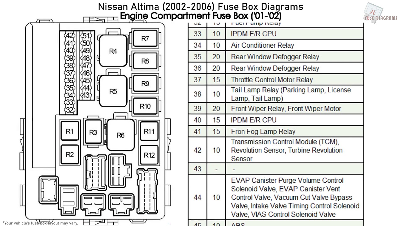
- Engine Compartment Fuse Box: Situated in the engine bay, often near the battery. This box protects critical engine components like the fuel pump, ignition system, and electronic control unit (ECU), also sometimes referred to as the powertrain control module (PCM).
Each fuse box contains a variety of fuses and relays. Fuses are designed to protect circuits from overcurrent by breaking the circuit when the current exceeds a safe level. Relays are electromechanical switches that control high-current circuits using a low-current signal. Relays are often used for components like headlights, horns, and fuel pumps.
The 2004 Altima uses standard blade-type fuses, color-coded according to their amperage rating. Common amperage ratings include 5A (ampere), 7.5A, 10A, 15A, 20A, 25A, and 30A. The fuse box cover usually has a legend indicating the amperage and function of each fuse. This legend is your first point of reference.
Decoding the Symbols: Lines, Colors, and Icons
Understanding the fuse box diagram requires deciphering its symbology. Here's a breakdown of common elements:
- Lines: Lines represent electrical circuits. Thicker lines may indicate higher current capacity circuits.
- Colors: Colors of the wires are usually not indicated on the fuse box diagram itself. Wire colors are present on the full wiring schematic.
- Icons: Icons represent the components that are protected by each fuse. Common icons include:
- Lightbulb: Indicates a lighting circuit (headlights, taillights, interior lights).
- Fan: Represents the blower motor for the climate control system.
- Radio: Represents the audio system.
- Cigar Lighter/Accessory Outlet: Indicates the power outlet.
- Engine Symbol: Usually refers to a sensor circuit, or PCM circuit.
- Fuse Numbers: Each fuse is assigned a unique number, cross-referenced to the legend on the fuse box cover.
- Amperage Rating: The amperage rating (e.g., 10A, 20A) is clearly marked for each fuse.
The diagram will typically show the fuse number, amperage, and the component it protects. Some diagrams may also indicate the wire color associated with the circuit, although this is less common on simplified fuse box diagrams.
How It Works: The Electrical Flow
The fuse box acts as a central distribution point for electrical power. Power flows from the battery to the ignition switch. Once the ignition is turned on, power is distributed through the fuse boxes to the various circuits in the vehicle. Each circuit is protected by a fuse. If a fault occurs (e.g., a short circuit), the current increases dramatically. This excessive current melts the fuse element, breaking the circuit and preventing damage to the protected component and the wiring.
Think of a fuse as a weak link in a chain. It's designed to break under stress, sacrificing itself to protect the more valuable components in the circuit.
Real-World Use: Basic Troubleshooting Tips
Here's how to use the fuse box diagram for troubleshooting:
- Identify the Problem: Determine which component is not working (e.g., the radio, a headlight).
- Consult the Diagram: Locate the fuse that protects the affected component on the fuse box diagram. The easiest way is to look at the legend on the fuse box cover.
- Inspect the Fuse: Physically check the fuse. A blown fuse will typically have a broken filament (the thin wire inside the fuse). Some fuses may also appear discolored or melted.
- Replace the Fuse: Replace the blown fuse with a new fuse of the exact same amperage rating. Never use a fuse with a higher amperage rating, as this could overload the circuit and cause damage or a fire.
- Test the Component: After replacing the fuse, test the component to see if it now works.
- If the Fuse Blows Again: If the new fuse blows immediately, there is a short circuit in the wiring or a faulty component. Further diagnosis is required to find and repair the short circuit. This may involve using a multimeter to check for continuity and resistance in the circuit.
A fuse puller tool, often included in the fuse box, can be helpful for removing and installing fuses without damaging them.
Safety First: Highlighting Risky Components
Working with electrical systems can be dangerous. Always observe the following safety precautions:
- Disconnect the Battery: Before working on any electrical circuit, disconnect the negative (-) terminal of the battery. This will prevent accidental shocks or short circuits.
- Never Use Higher Amperage Fuses: As mentioned earlier, using a fuse with a higher amperage rating can overload the circuit and cause a fire.
- Avoid Wet Conditions: Never work on electrical systems in wet or damp conditions.
- Consult a Professional: If you're not comfortable working on electrical systems, consult a qualified mechanic.
Be particularly cautious when working with circuits related to the airbag system or the anti-lock braking system (ABS). These systems can be sensitive to electrical disturbances, and improper handling can lead to malfunction or accidental deployment of the airbags.
Remember, the fuse box diagram is a tool, and like any tool, it's most effective when used with knowledge and caution. Take the time to understand your Altima's electrical system, and you'll be well-equipped to handle minor repairs and modifications with confidence.
We have a copy of the 2004 Nissan Altima Fuse Box Diagram available for download. You can use this diagram to effectively trace circuits and perform electrical work with confidence. It will prove invaluable for diagnosing issues or installing aftermarket electrical accessories.