05 Nissan Altima Fuse Box Diagram
If you're wrenching on a 2005 Nissan Altima, understanding its fuse box diagram is absolutely crucial. Whether you're troubleshooting a blown fuse, diagnosing electrical issues, or even adding aftermarket accessories, a good understanding of the fuse box is paramount. This article will delve into the specifics of the 2005 Altima fuse box diagram, providing you with the knowledge to confidently tackle electrical tasks on your vehicle.
Purpose of the Fuse Box Diagram
The fuse box diagram serves as your roadmap to the electrical system. Think of it as the index to a vast book of circuits. Its primary purposes include:
- Troubleshooting Electrical Problems: Identifying which fuse protects a specific circuit allows you to quickly pinpoint the source of a malfunctioning component. If your headlights suddenly stop working, the diagram will guide you to the headlight fuse.
- Safe Fuse Replacement: Incorrectly replacing a fuse can damage components. The diagram ensures you use the correct amperage fuse, preventing overload and potential fire hazards.
- Adding Aftermarket Accessories: If you're installing a new stereo, amplifier, or lights, you'll need to tap into the car's electrical system. The diagram shows you where to find appropriate circuits for power and ground.
- Understanding the Vehicle's Electrical System: Simply studying the diagram can give you a better grasp of how different components are interconnected and powered.
Key Specs and Main Parts
The 2005 Nissan Altima typically has two main fuse boxes. One is located inside the cabin, usually under the dashboard on the driver's side. The other is in the engine compartment, often near the battery.
Interior Fuse Box
This fuse box primarily protects circuits related to interior components such as:
- Interior Lights
- Radio
- Power Windows
- Power Door Locks
- Windshield Wipers
- Climate Control System
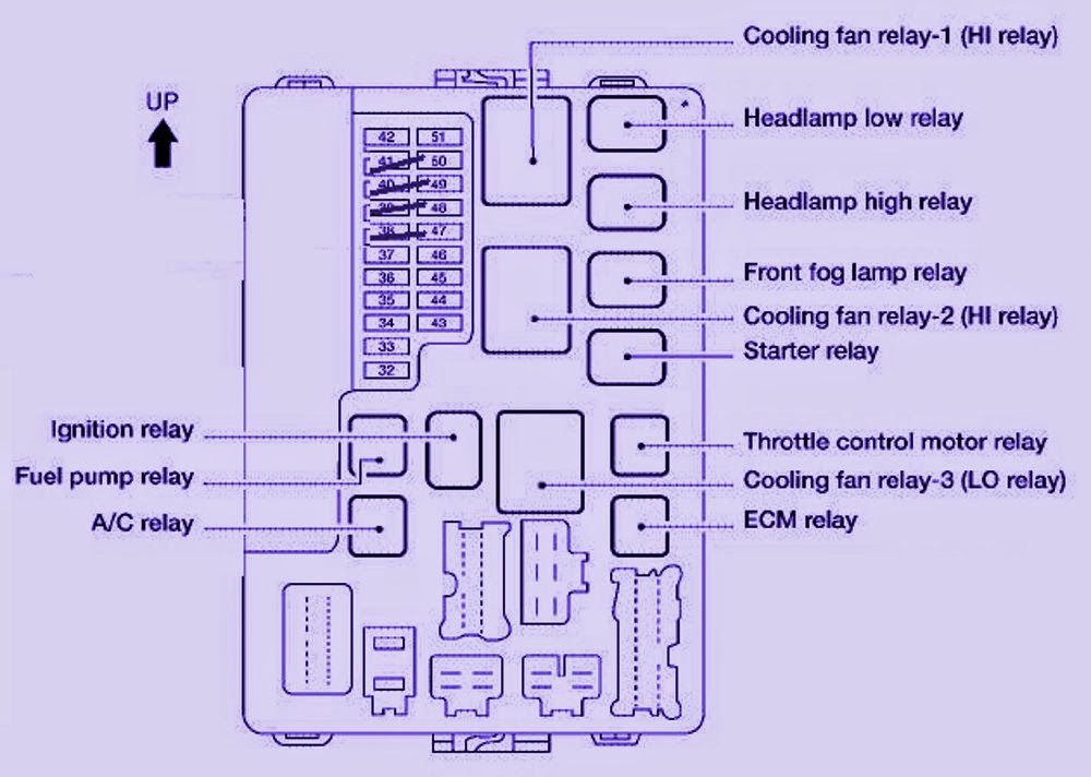
Engine Compartment Fuse Box
This fuse box handles more demanding circuits, including:
- Headlights
- Tail Lights
- Turn Signals
- Engine Control Unit (ECU) – The “brain” of the engine
- Anti-lock Braking System (ABS)
- Fuel Pump
- Cooling Fan
Each fuse box will contain a variety of fuses and relays. Fuses are sacrificial devices designed to break a circuit when the current exceeds a safe level, preventing damage to components. Relays are electrically operated switches that allow a low-current circuit to control a high-current circuit. For example, the headlight switch uses a low-current signal to activate a relay that switches on the high-current headlights.
Understanding Fuse Box Diagram Symbols
Fuse box diagrams aren't just a list of components; they use symbols to represent different elements and connections. Understanding these symbols is essential for accurately interpreting the diagram.
Lines
- Solid Lines: Typically represent direct electrical connections or wiring.
- Dotted Lines: May indicate a ground connection or a shared connection between multiple circuits.
Colors
Wire colors are crucial for identifying specific wires in the harness. The diagram will often include a color code legend. Common colors include:
- Red: Often indicates a positive (power) wire.
- Black: Usually represents a ground wire.
- Other Colors (Blue, Yellow, Green, White, etc.): These colors are used for various circuits, and the diagram legend will specify their function.
Icons
Icons represent the protected components or circuits. Some common icons include:
- Light Bulb: Represents headlights, taillights, or interior lights.
- Fan: Indicates a cooling fan or blower motor.
- Radio Symbol: Indicates the radio or audio system.
- Windshield Wiper Symbol: Represents the windshield wiper motor.
- Engine Symbol: May represent the engine control unit (ECU) or other engine-related components.
Amperage Ratings: Each fuse will have an amperage rating (e.g., 10A, 15A, 20A). This indicates the maximum current the fuse can handle before blowing. The diagram will specify the correct amperage for each fuse location. Always replace a blown fuse with one of the same amperage rating.
How It Works: From Fuse to Component
The fuse box acts as a central distribution point for electrical power. Power from the battery flows into the fuse box, and the fuses protect each circuit from overcurrent. When a circuit draws too much current (due to a short circuit, a faulty component, or an overload), the fuse blows, interrupting the flow of electricity and preventing damage.
Let's consider an example: the headlights. When you turn on the headlight switch, the switch sends a signal to a relay (usually). This relay then closes, allowing power to flow from the battery, through the appropriate fuse in the fuse box, and to the headlights. If there's a short circuit in the headlight wiring, the current will surge, causing the headlight fuse to blow and cutting off power to the headlights.
Real-World Use: Basic Troubleshooting Tips
Here are some basic troubleshooting tips using the fuse box diagram:
- Identify the Problem: Determine which component isn't working.
- Consult the Diagram: Locate the fuse that protects the malfunctioning component using the fuse box diagram.
- Inspect the Fuse: Remove the fuse and visually inspect it. A blown fuse will typically have a broken filament inside. You can also use a multimeter to test for continuity.
- Replace the Fuse: If the fuse is blown, replace it with a new fuse of the same amperage rating.
- Test the Component: Turn on the component to see if it now works.
- If the Fuse Blows Again: If the new fuse blows immediately, there's likely a short circuit in the wiring or a faulty component. This requires further diagnosis and repair. Don't just keep replacing fuses.
Safety Considerations
Working with electrical systems can be dangerous. Here are some important safety precautions:
- Disconnect the Battery: Before working on the fuse box or any electrical components, disconnect the negative terminal of the battery. This will prevent accidental shorts and electrical shocks.
- Use the Correct Fuse Rating: Never replace a fuse with one of a higher amperage rating. This can overload the circuit and cause a fire.
- Avoid Water: Keep the fuse box and surrounding area dry. Water can cause short circuits and corrosion.
- Be Careful with Relays: Relays can get hot during operation. Avoid touching them immediately after the vehicle has been running.
- Consult a Professional: If you're not comfortable working with electrical systems, consult a qualified mechanic. Incorrect wiring can damage your vehicle and pose a safety hazard. Working on systems like the ABS or airbag system can be dangerous and should be left to professionals.
The ABS or airbag system are critical safety systems and should not be tampered with unless you have experience and specialized knowledge.
By carefully studying the 2005 Nissan Altima fuse box diagram and following these guidelines, you can confidently troubleshoot electrical problems, add accessories, and better understand your vehicle's electrical system.
We have the complete fuse box diagram available for download. It contains high-resolution images and detailed descriptions of each fuse and relay location.