05 Nissan Maxima Fuse Box Diagram
Let's dive into the fuse box diagram for a 2005 Nissan Maxima. This isn't just a piece of paper; it's your roadmap to electrical troubleshooting, modifications, and even preventing small problems from escalating into costly repairs. Think of it as the Rosetta Stone for your car's electrical system.
Purpose: Why This Diagram Matters
Understanding your 2005 Maxima's fuse box diagram empowers you to:
- Diagnose Electrical Issues: Quickly identify which fuse controls a malfunctioning component, saving you time and money on unnecessary mechanic visits.
- Perform Basic Repairs: Replacing a blown fuse is often a simple fix. The diagram tells you which fuse to check and its amperage rating.
- Install Aftermarket Accessories: Safely tap into the electrical system for things like auxiliary lights, stereos, or remote starters. Knowing the circuit load is crucial to avoid overloading and damaging your car.
- Understand Your Car's Electrical System: Gain a deeper understanding of how different components are powered and protected.
Key Specs and Main Parts
The 2005 Nissan Maxima typically has two primary fuse box locations:
- Inside the Cabin (Instrument Panel): Located under the dashboard, usually on the driver's side, this fuse box houses fuses for interior components like the radio, power windows, lights, and the cigarette lighter (power outlet).
- Under the Hood (Engine Compartment): Situated near the battery, this fuse box contains fuses and relays for critical engine and drivetrain components like the engine control module (ECM), fuel pump, ignition system, and anti-lock braking system (ABS).
Each fuse box contains several elements:
- Fuses: These are the sacrificial elements, designed to blow and break the circuit when an overcurrent occurs, protecting more expensive components. Fuses are rated in amperes (amps), which indicate the maximum current they can handle.
- Relays: These are electrically operated switches. A small current can control a much larger current. Relays are used for components that require a lot of power, such as the headlights, starter motor, and air conditioning compressor.
- Fuse Puller: Often included in the fuse box, this tool makes removing fuses much easier and prevents damage.
- Spare Fuses: Usually, the fuse box contains spare fuses of different amperage ratings for replacement.
- The Diagram (Label): A printed label, typically on the inside of the fuse box cover, showing the location and function of each fuse and relay. This is the critical piece of information we're discussing.
Symbols: Deciphering the Diagram
The fuse box diagram isn't just a grid of squares; it's a symbolic representation of the electrical system. Understanding the symbols is key to using it effectively.
- Lines: Represent electrical circuits (wiring). Thicker lines might indicate higher current-carrying capacity.
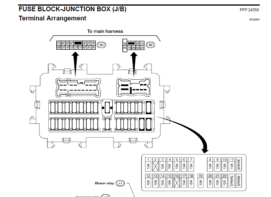
- Squares/Rectangles: Represent fuses. The number inside or next to the square indicates the fuse's amperage rating (e.g., "10A" means 10 amps).
- Circles/Ovals: Usually represent relays.
- Icons: These are graphical representations of the component being protected by the fuse. For example:
- A light bulb icon indicates a fuse for the headlights or taillights.
- A steering wheel icon might indicate a fuse for the power steering system.
- A fan icon could represent the radiator fan or the climate control blower motor.
- A radio icon represents the radio fuse.
- Colors: While not always consistent, some manufacturers use colors to differentiate between fuse amperage ratings. Common examples:
- Yellow: Often indicates 20 amp fuses.
- Red: Typically represents 10 amp fuses.
- Blue: Often used for 15 amp fuses.
How It Works: The Fuse's Role in the Circuit
Imagine the electrical system as a series of water pipes. The battery is the water source (voltage), and the wires are the pipes. The electrical components (lights, motors, etc.) are devices using the water flow (current). A fuse is a thin, weak section in one of these pipes.
Under normal operating conditions, the current flows safely through the fuse. However, if a short circuit occurs (e.g., a wire rubs against the chassis, creating a low-resistance path to ground) or if a component draws excessive current (e.g., a motor starts to fail and requires more power to operate), the current flow dramatically increases. This surge of current heats up the thin metal strip inside the fuse. When the current exceeds the fuse's amperage rating, the strip melts, breaking the circuit and stopping the flow of electricity. This prevents damage to the wiring and the component itself.
Think of it as a circuit breaker in your house. When overloaded, the breaker trips, cutting off the power. The fuse does the same thing but on a smaller scale and is a single-use device – it must be replaced after blowing.
Real-World Use: Basic Troubleshooting Tips
Here's how to use the fuse box diagram to troubleshoot a problem:
- Identify the Problem: What's not working? Be specific (e.g., "The radio doesn't turn on," not just "Something electrical is wrong").
- Consult the Diagram: Locate the fuse box diagram. Find the fuse that corresponds to the non-functional component. Note that some components may have more than one fuse, and those fuses may be in either the interior or the engine compartment fuse box!
- Inspect the Fuse: Use the fuse puller to remove the fuse. Visually inspect it. A blown fuse will typically have a broken filament – you'll see a gap in the wire inside the fuse. Sometimes, it might look cloudy or blackened.
- Test the Fuse (Recommended): Use a multimeter set to continuity mode. Touch the probes to each side of the fuse. A good fuse will show continuity (a beep or a near-zero resistance reading). A blown fuse will show no continuity.
- Replace the Fuse: If the fuse is blown, replace it with a new fuse of the exact same amperage rating. Never use a fuse with a higher amperage rating. This could damage the wiring and the component it's supposed to protect, and could potentially cause a fire.
- Test Again: Turn on the component to see if it now works.
- If the Fuse Blows Again: If the new fuse blows immediately or shortly after replacement, there's a larger problem in the circuit, such as a short circuit or a failing component. Further diagnostics are needed. Don't just keep replacing fuses; you're masking a bigger issue. Seek professional help.
Safety: Handling Risky Components
Working with electrical systems carries inherent risks. Here are some safety precautions:
- Disconnect the Battery (Recommended): Before working on any electrical component, disconnect the negative terminal of the battery. This eliminates the risk of accidental short circuits.
- Use the Right Tools: Use a fuse puller to remove fuses. Don't use pliers or screwdrivers, as you could damage the fuse box or the fuses.
- Never Bypass a Fuse: Never replace a fuse with a wire or a piece of metal. This removes the safety protection and could lead to a fire.
- Work in a Well-Lit Area: Good visibility is essential for safety.
- Avoid Wet Conditions: Never work on electrical systems in wet conditions.
- Be Careful Around Relays: Relays control high-current circuits. Be cautious when handling them.
- High-Current Fuses: The high-current fuses and fusible links found near the battery are especially dangerous. If these blow frequently, the underlying problem should be addressed by a qualified technician. These protect the entire car's electrical system and potential failures there can be catastrophic.
Remember, if you're unsure about any step, consult a qualified mechanic. Electricity can be dangerous, and it's always better to be safe than sorry.
We have access to the complete 2005 Nissan Maxima fuse box diagram. You can download it for your reference and troubleshooting needs. Good luck, and stay safe while working on your Maxima!