06 Nissan Altima Fuse Box Diagram
For the intermediate car owner, modder, or DIY mechanic tackling electrical projects on a 2006 Nissan Altima, understanding the fuse box diagram is absolutely crucial. This isn't just about replacing a blown fuse; it's about diagnosing electrical issues, safely adding aftermarket accessories, and gaining a deeper understanding of your vehicle's electrical system. This article will provide a comprehensive guide to deciphering the 2006 Nissan Altima fuse box diagram.
Purpose of Understanding the Fuse Box Diagram
Why bother learning to read a fuse box diagram? Here's why it's a valuable skill:
- Troubleshooting Electrical Problems: When a component like your headlights, radio, or power windows stops working, the first place to check is the fuse box. The diagram pinpoints the exact fuse associated with that circuit.
- Preventing Further Damage: Replacing a blown fuse with one of a higher amperage (a common mistake) can overload the circuit and cause significant damage to wiring and components. Knowing the correct fuse size is vital.
- Adding Aftermarket Accessories: If you're installing a new sound system, auxiliary lights, or other electrical accessories, you'll need to tap into the car's electrical system. The diagram helps you identify suitable circuits for powering your additions safely and efficiently.
- Learning Vehicle Electrical Systems: Studying the fuse box diagram is a great way to understand how different electrical components are connected and protected within your car.
Key Specs and Main Parts of the 2006 Nissan Altima Fuse Boxes
The 2006 Nissan Altima typically has two main fuse box locations:
- Interior Fuse Box: Located inside the cabin, usually under the dashboard on the driver's side (though sometimes on the passenger's side). This box generally houses fuses for interior components like lights, radio, power windows, and the cigarette lighter/power outlet.
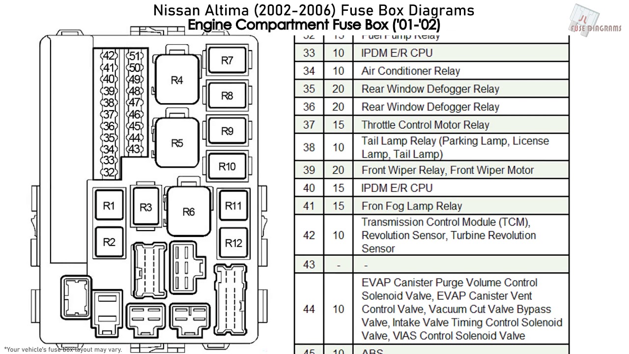
- Engine Compartment Fuse Box: Found under the hood, this fuse box contains fuses and relays for critical engine and vehicle systems, such as the fuel pump, ignition system, headlights, and anti-lock braking system (ABS).
Each fuse box contains:
- Fuses: Small, replaceable devices designed to protect electrical circuits from overcurrent. They contain a thin wire that melts and breaks the circuit if the current exceeds a safe level. Fuses are rated in amperes (amps), indicating the amount of current they can handle before blowing.
- Relays: Electrically operated switches that allow a low-current circuit to control a high-current circuit. They're often used for components that require a lot of power, such as the headlights and starter motor.
- Fuse Puller: A small plastic tool used to safely remove and replace fuses without damaging them. Often integrated into the fuse box cover.
- The Diagram (Label): Usually located on the inside of the fuse box cover or in the owner's manual, the diagram shows the location of each fuse and relay and its corresponding function and amperage rating. This is the core element we're focusing on.
Symbols, Lines, Colors, and Icons Explained
Fuse box diagrams aren't always straightforward, but understanding the common symbols is key:
- Fuse Symbols: Fuses are typically represented by a rectangular box with a number inside, indicating the amperage rating (e.g., "10A" for a 10-amp fuse).
- Relay Symbols: Relays are often depicted as squares or rectangles with internal lines representing the switch contacts and coil. The diagram may include labels like "Headlight Relay" or "Fuel Pump Relay."
- Lines and Colors: These may represent wiring harnesses and circuit pathways. Some diagrams may use colors to differentiate between different types of circuits or voltage levels. However, color-coding is not universally used on fuse box diagrams themselves.
- Icons: Some diagrams use icons to represent the function of the fuse or relay. Common icons include a light bulb for headlights, a radio for the audio system, a window for power windows, and a steering wheel for power steering. Pay close attention to the legend (if present) which translates these icons.
- Numerical Listings: Most diagrams include a numbered list corresponding to each fuse or relay location. These numbers are physically stamped near the fuse slots in the fuse box.
How It Works: The Circuit Protection Principle
The fuse box is the heart of your Altima's electrical protection system. Each fuse protects a specific circuit. A circuit is a closed loop that allows electricity to flow from the battery, through a component (like a headlight), and back to the battery. If there's a fault in the circuit – for example, a short circuit where a wire accidentally touches the chassis (ground) – the current flow will increase dramatically. This sudden surge of current could damage the wiring, components, and even start a fire. The fuse prevents this by sacrificing itself. The thin wire inside the fuse melts, breaking the circuit and stopping the flow of electricity before any damage can occur. It's a deliberate weak link designed to protect the rest of the system.
Relays, on the other hand, act as electrically controlled switches. They're used when the circuit being controlled requires a high current that could overwhelm a small switch in the cabin. For example, the headlight switch in your car sends a small signal to the headlight relay, which then closes the high-current circuit to power the headlights. This setup allows a small, low-current switch to control a powerful device.
Real-World Use: Basic Troubleshooting Tips
Here's how to use the fuse box diagram for troubleshooting:
- Identify the Problem: Determine which component is not working.
- Consult the Diagram: Locate the fuse or relay associated with the non-functional component on the fuse box diagram. Refer to your owner's manual as needed.
- Inspect the Fuse: Using the fuse puller, carefully remove the fuse. Visually inspect it. A blown fuse will have a broken filament (the thin wire inside).
- Replace the Fuse: If the fuse is blown, replace it with a new fuse of the exact same amperage rating. Using a higher amperage fuse is dangerous and can cause serious damage.
- Test the Component: After replacing the fuse, test the component to see if it's working. If the fuse blows again immediately, there's a deeper problem in the circuit that needs further investigation. It could indicate a short circuit or a faulty component.
- Relay Testing: Relays are a bit trickier to test. You can often swap a relay with an identical one from a less critical system (like the rear window defogger) to see if that resolves the problem. If it does, the original relay is likely faulty. More advanced testing requires a multimeter and knowledge of relay circuits.
Safety Considerations
Working with electrical systems can be dangerous. Keep these safety tips in mind:
- Disconnect the Battery: Before working on any electrical components, disconnect the negative (-) terminal of the battery to prevent accidental shocks or short circuits. This is especially important when working with the engine compartment fuse box.
- Use the Correct Fuses: Always replace a blown fuse with one of the exact same amperage rating. Using a higher amperage fuse can overload the circuit and cause a fire.
- Avoid Water: Never work on electrical components in wet conditions. Water is an excellent conductor of electricity and can create a shock hazard.
- Be Careful with High-Voltage Components: Some components, such as the ignition system and fuel injection system, operate at high voltages. Avoid touching these components when the engine is running or the ignition is on.
- Consult a Professional: If you're not comfortable working on electrical systems, or if you're unsure about anything, consult a qualified mechanic. Electrical problems can be complex and dangerous.
- Airbag circuits (if equipped) are especially sensitive! Mishandling these can lead to accidental deployment, resulting in serious injury. Avoid disturbing any wiring or connectors related to airbags.
By understanding the fuse box diagram and following these safety guidelines, you can confidently tackle many electrical repairs and modifications on your 2006 Nissan Altima.
We have the 2006 Nissan Altima Fuse Box Diagram available for download. This comprehensive file includes detailed layouts of both the interior and engine compartment fuse boxes, along with fuse amperage ratings and component assignments. This resource will significantly aid in your troubleshooting and electrical projects.