07 Tundra 2007 Toyota Tundra Fuse Box Diagram
The 2007 Toyota Tundra is a rugged and reliable truck, but even the toughest vehicles can experience electrical issues. Understanding the fuse box and its components is crucial for diagnostics, repairs, and even simple modifications. This guide provides an in-depth look at the 2007 Tundra's fuse box diagram, equipping you with the knowledge to confidently tackle electrical troubleshooting and repairs.
Purpose of a Fuse Box Diagram
A fuse box diagram is essentially a roadmap of your vehicle's electrical system. It visually represents the location of each fuse and relay, along with the circuit it protects. This diagram is invaluable for several reasons:
- Troubleshooting Electrical Problems: When an electrical component fails (e.g., a headlight, radio, or power window), the first step is often to check the corresponding fuse. The diagram allows you to quickly locate the correct fuse for inspection.
- Performing Repairs: After identifying a blown fuse, the diagram helps you understand which circuit is affected, guiding you toward potential sources of the problem (e.g., a short circuit in the wiring).
- Installing Accessories: Adding aftermarket accessories, such as lights or audio systems, often requires tapping into existing circuits. The diagram enables you to identify suitable power sources and ensure proper fuse protection for the new components.
- Learning Your Vehicle's Electrical System: Studying the diagram provides a fundamental understanding of how different electrical systems are interconnected in your Tundra.
Key Specs and Main Parts
The 2007 Tundra typically has two main fuse box locations:
- Interior Fuse Box: Located under the dashboard, usually on the driver's side. This fuse box primarily protects circuits related to interior components like the radio, power windows, dome lights, and instrument panel.
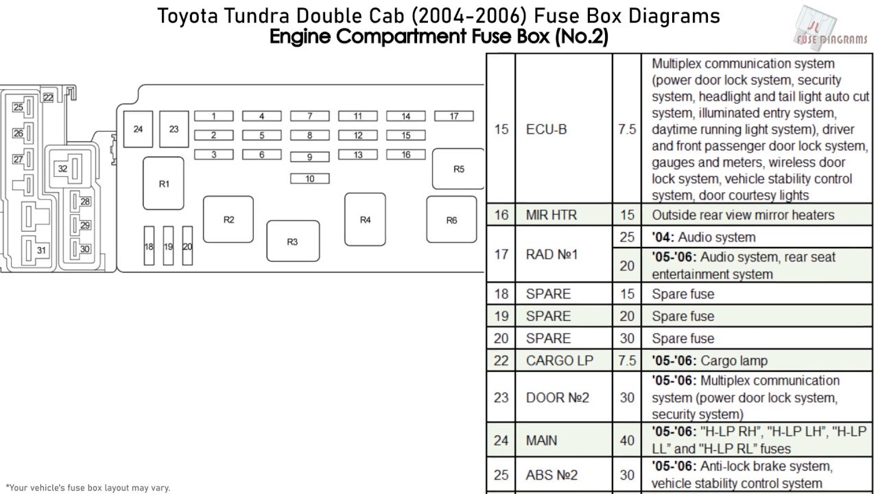
- Engine Compartment Fuse Box: Located in the engine bay, usually near the battery. This fuse box protects circuits related to engine management, headlights, horn, anti-lock brakes (ABS), and other critical vehicle systems.
Key components found within these fuse boxes include:
- Fuses: These are sacrificial devices designed to protect electrical circuits from overcurrent. They consist of a thin metal strip that melts and breaks the circuit if the current exceeds a predetermined limit. Fuses are rated in amperes (amps or A), indicating the amount of current they can safely handle.
- Relays: Relays are electromagnetic switches that control high-current circuits using a low-current signal. They are often used for components like headlights, starter motors, and air conditioning compressors. Relays consist of a coil, an armature, and contacts. When the coil is energized, it creates a magnetic field that pulls the armature, closing the contacts and completing the circuit.
- Circuit Breakers: Similar to fuses, circuit breakers protect circuits from overcurrent. However, instead of melting, they trip, interrupting the circuit. Unlike fuses, circuit breakers can be reset after the fault is cleared. They are often used for high-current circuits like power seats and windows.
- Fuse Puller: A small plastic tool used to safely remove and install fuses.
Understanding Fuse Box Diagram Symbols
Fuse box diagrams use a combination of lines, colors, and icons to represent different components and circuits. While the specific symbols can vary slightly, some common conventions are:
- Lines: Lines represent electrical wires connecting different components. Thicker lines may indicate larger gauge wires used for higher current circuits.
- Colors: Wire colors are often indicated on the diagram. Color coding helps in identifying specific wires and tracing circuits. Common colors include red (power), black (ground), and various other colors for different signal and control wires.
- Icons: Icons are used to represent different electrical components. Examples include:
- Headlight icon: Represents the headlight circuit.
- Radio icon: Represents the radio circuit.
- Window icon: Represents the power window circuit.
- Engine icon: Represents engine management-related circuits.
- Fuse Ratings: Each fuse is labeled with its amperage rating (e.g., 10A, 15A, 20A). This indicates the maximum current the fuse can handle before blowing.
- Circuit Descriptions: The diagram typically includes a brief description of the circuit protected by each fuse or relay. This helps in identifying the correct fuse for a specific component.
How It Works: Electrical Protection and Circuitry
The fuse box serves as the central protection point for your Tundra's electrical system. Each circuit is protected by a fuse or circuit breaker that is sized appropriately for the expected current draw of the components in that circuit. When an overcurrent condition occurs (e.g., due to a short circuit or a malfunctioning component), the fuse blows or the circuit breaker trips, interrupting the flow of electricity and preventing damage to the wiring and other components.
Relays are used to control high-current circuits with a low-current signal. For example, the headlight switch in your dashboard doesn't directly control the high current needed to power the headlights. Instead, it sends a low-current signal to a relay, which then closes the circuit and allows the high current to flow to the headlights. This design protects the headlight switch from damage and allows for more efficient control of high-power components.
Real-World Use: Basic Troubleshooting Tips
Here are some basic troubleshooting tips using the fuse box diagram:
- Symptom: A specific electrical component is not working (e.g., the radio).
- Locate the interior fuse box.
- Consult the fuse box diagram to identify the fuse associated with the radio.
- Use a fuse puller to remove the fuse.
- Inspect the fuse. If the metal strip inside is broken, the fuse is blown.
- Replace the blown fuse with a new fuse of the same amperage rating. Never use a fuse with a higher rating, as this could damage the circuit.
- If the new fuse blows immediately, there is likely a short circuit in the wiring or a faulty component. Further diagnosis is required.
- Symptom: Multiple electrical components are not working.
- Check the main fuses or fusible links in the engine compartment fuse box. These protect entire sections of the electrical system.
- Look for common ground points and inspect them.
Remember to always use the correct fuse amperage rating. Using a higher amperage fuse can allow excessive current to flow, potentially causing damage to wiring, components, and even creating a fire hazard. A lower amperage fuse will blow prematurely, causing the circuit to malfunction.
Safety Considerations
Working with automotive electrical systems can be dangerous. Always follow these safety precautions:
- Disconnect the battery: Before working on any electrical components, disconnect the negative (black) battery cable to prevent accidental short circuits.
- Use insulated tools: Use tools with insulated handles to protect yourself from electric shock.
- Avoid working in wet conditions: Water can conduct electricity and increase the risk of electric shock.
- Identify risky components: The starter motor, alternator, and ABS system involve high current and voltage. Exercise extreme caution when working on these systems. The SRS (Supplemental Restraint System) or airbag system also has components that, if mishandled, can cause injury. It's generally best to leave SRS repairs to qualified professionals.
- Never bypass a fuse: Bypassing a fuse with a wire or other conductive material can create a serious fire hazard.
Disclaimer: This guide provides general information and should not be considered a substitute for professional automotive repair advice. If you are not comfortable working on your vehicle's electrical system, consult a qualified mechanic.
We have a detailed 2007 Toyota Tundra fuse box diagram available for download. This diagram provides precise locations, amperage ratings, and circuit descriptions for all fuses and relays in both the interior and engine compartment fuse boxes. Having this resource at your fingertips will greatly simplify electrical troubleshooting and repairs on your Tundra.