
12 Volt Starter Solenoid Wiring Diagram
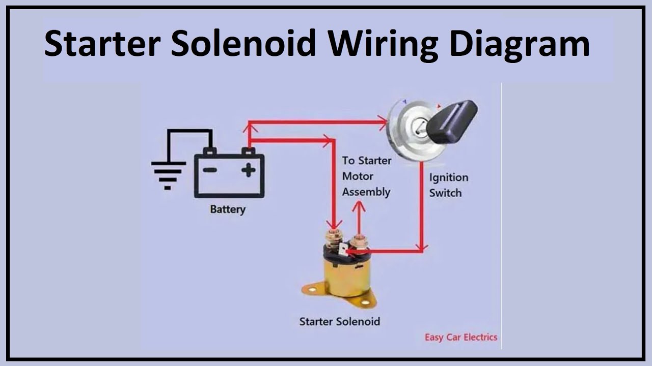
Understanding the 12-volt starter solenoid wiring diagram is crucial for any intermediate car owner, modder, or DIY mechanic looking to tackle electrical repairs, diagnose starting issues, or even customize their vehicle's starting system. This article will break down the intricacies of the diagram, explaining its purpose, key components, how it works, and some real-world troubleshooting tips.
Why This Diagram Matters
The starter solenoid is a critical component in your vehicle's starting system. It acts as a relay, using a small electrical signal from the ignition switch to control a much larger current flow to the starter motor. A clear understanding of the wiring diagram empowers you to:
- Diagnose Starting Problems: Quickly pinpoint faulty wiring, a bad solenoid, or a failing ignition switch when your car won't start.
- Perform Repairs Confidently: Replace a damaged solenoid or repair corroded wiring knowing exactly where each wire connects.
- Customize Your Vehicle: Integrate aftermarket components or modify the starting system with precision.
- Understand Electrical Systems: Enhance your overall knowledge of automotive electrical systems.
Key Specs and Main Parts
Before diving into the diagram itself, let's define the key components and their specifications:
Main Components:
- Battery: Typically a 12-volt battery, providing the main power source. Its capacity is measured in Cold Cranking Amps (CCA), indicating its ability to deliver current in cold temperatures.
- Ignition Switch: The key-operated switch that sends a signal to the solenoid when you turn the key to the "start" position.
- Starter Solenoid: An electromagnetic switch that closes a high-current circuit to the starter motor when energized. It typically has two large terminals for the battery and starter motor connections and one or two smaller terminals for the control signal from the ignition switch and sometimes a ground connection.
- Starter Motor: An electric motor that turns the engine's flywheel to initiate the combustion process.
- Ground Connection: A secure connection between the vehicle's chassis and the negative terminal of the battery, providing a return path for the electrical current.
- Fuse(s) / Fusible Link(s): Safety devices that protect the electrical system from overcurrent.
Key Specifications:
- Voltage: Most automotive systems operate at 12 volts DC (Direct Current).
- Amperage: The starter motor draws a significant amount of current, often exceeding 100 amps during startup. The solenoid is designed to handle this high current.
- Wire Gauge: The thickness of the wiring is critical for handling the current flow. Thicker wires (lower gauge numbers) are required for high-current circuits. The battery cable and the cable between the solenoid and the starter motor are typically very thick (e.g., 4 gauge or thicker).
Symbols: Decoding the Diagram
Understanding the symbols used in the wiring diagram is essential for interpreting its information:
- Solid Lines: Represent wires. The thickness of the line may or may not indicate wire gauge in some diagrams.
- Dashed Lines: Often represent ground connections or less critical wiring.
- Colors: Each wire is typically identified by a color code (e.g., Red, Black, Blue, Yellow). This helps you trace wires in the vehicle. Refer to the diagram's legend for specific color meanings.
- Component Symbols: Each component (battery, solenoid, starter motor, ignition switch) is represented by a standardized symbol. Familiarize yourself with these symbols.
- Ground Symbol: Usually represented by a series of horizontal lines that taper downwards, indicating a connection to the vehicle's chassis.
- Fuse Symbol: Typically represented by a zigzag line enclosed in a rectangle.
Common Color Codes: While not universal, certain color codes are frequently used:
- Red: Usually indicates a positive (+) connection from the battery.
- Black: Usually indicates a ground (-) connection.
- Yellow/Green: Often used for circuits originating from the ignition switch.
- Other Colors: Vary depending on the specific vehicle and circuit.
How It Works: The Starting Sequence
The starter solenoid wiring diagram illustrates the flow of electricity during the starting sequence:
- Key Turn: When you turn the ignition key to the "start" position, a small current flows from the battery, through the ignition switch, and to the small control terminal on the starter solenoid.
- Solenoid Activation: The small current energizes the solenoid's internal coil, creating a magnetic field. This magnetic field pulls a plunger or lever that closes the high-current contacts within the solenoid.
- High-Current Flow: Closing the contacts completes the high-current circuit between the battery and the starter motor.
- Starter Motor Engagement: The starter motor engages the engine's flywheel, turning the crankshaft and initiating the combustion process.
- Key Release: When you release the key, the current to the solenoid is interrupted, the magnetic field collapses, and the high-current contacts open, disconnecting the starter motor.
Important Note: Some vehicles use a separate relay in the starting circuit in addition to the solenoid. This relay is often located near the starter solenoid and helps reduce the load on the ignition switch.
Real-World Use: Basic Troubleshooting
Here are some basic troubleshooting tips using the wiring diagram:
- No Click, No Start:
- Check the battery voltage. Is it at least 12.6 volts?
- Inspect the wiring to the solenoid for corrosion or damage. Clean and tighten connections.
- Test the ignition switch. Does it send power to the solenoid when turned to "start"? Use a multimeter to check for voltage at the small terminal of the solenoid.
- Test the solenoid itself. You can often apply direct power to the small terminal to see if the solenoid clicks and engages. If it doesn't, the solenoid is likely faulty.
- Click, No Start:
- The solenoid is engaging, but the starter motor isn't turning. This could indicate a faulty starter motor, a bad connection in the high-current circuit, or a low battery.
- Check the voltage at the starter motor while attempting to start the engine. If the voltage drops significantly, there may be a problem with the battery cable or the starter motor itself.
- Starter Motor Keeps Running:
- This is a serious problem and could damage the starter motor or flywheel. Immediately disconnect the battery to prevent further damage.
- The solenoid contacts may be stuck in the closed position. Replace the solenoid.
- The ignition switch may be faulty and not releasing the "start" signal.
Safety: Handling Risky Components
Working with the starter solenoid and its associated wiring involves high currents and potential hazards:
- Disconnect the Battery: Always disconnect the negative battery terminal before working on any part of the electrical system. This prevents accidental shorts and potential electric shock.
- High-Current Components: The battery cable and the cable between the solenoid and the starter motor carry very high currents. Be extremely careful when handling these components. Wear appropriate safety glasses and gloves.
- Short Circuits: Avoid creating short circuits. A short circuit can generate a large amount of heat and potentially start a fire.
- Proper Tools: Use insulated tools designed for automotive electrical work.
- Consult a Professional: If you are unsure about any aspect of the repair, consult a qualified mechanic.
By understanding the 12-volt starter solenoid wiring diagram, you can confidently diagnose and repair starting problems, customize your vehicle's electrical system, and enhance your overall automotive knowledge. Remember to prioritize safety and consult a professional if needed.
We have a detailed starter solenoid wiring diagram file available for download. This diagram provides a clear visual representation of the system, including color codes and component locations.