
12v 4 Pin Rocker Switch Wiring Diagram
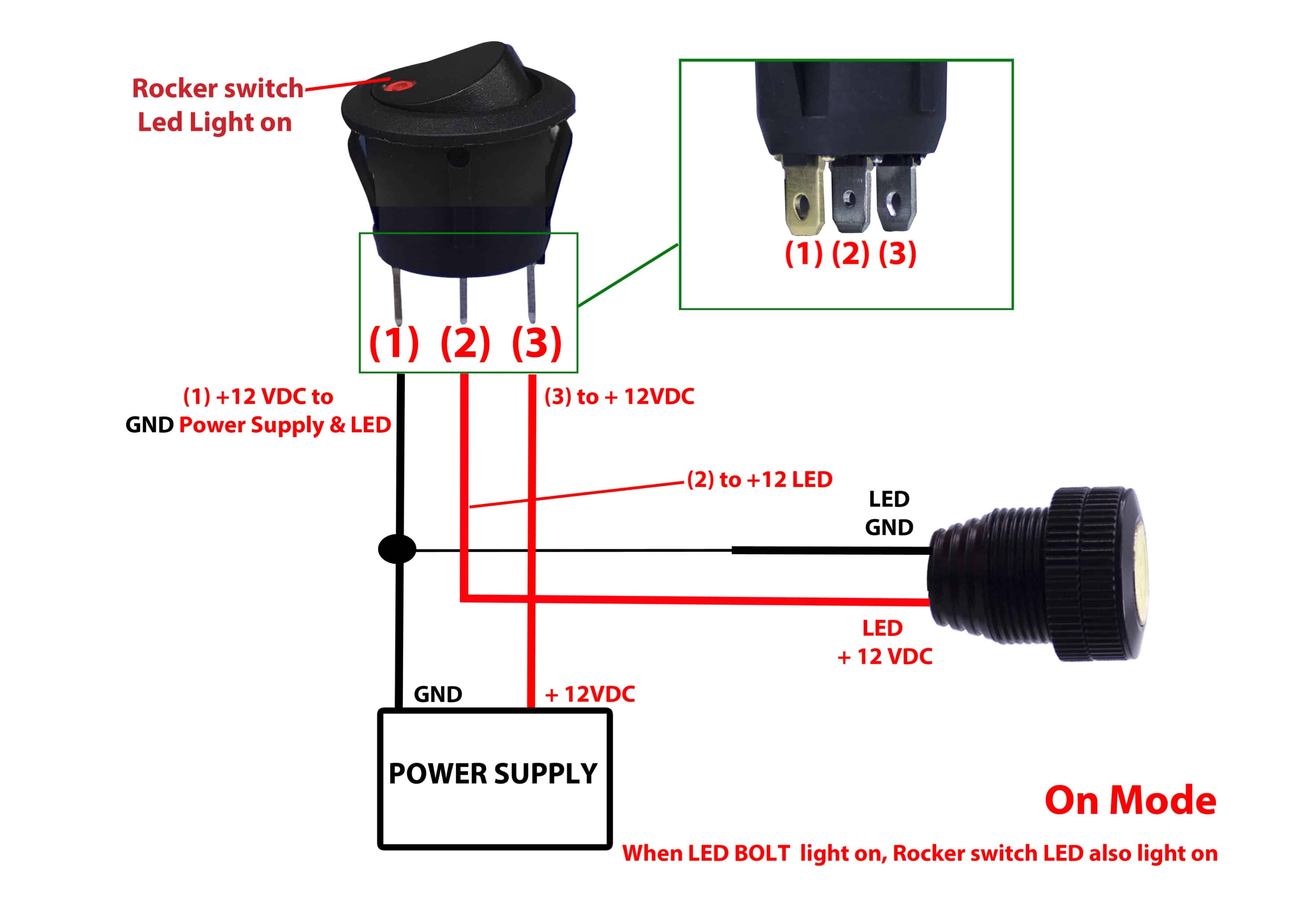
So, you're looking to wire up a 12V 4-pin rocker switch? Excellent choice. These switches are incredibly versatile and used in countless automotive applications, from adding auxiliary lights to controlling air compressors. Understanding the wiring diagram is absolutely crucial for a safe and functioning installation. This article will break down the diagram, explain its components, and give you the knowledge to confidently tackle your project.
Why This Diagram Matters
Having a clear understanding of your rocker switch wiring diagram isn't just about getting the job done; it's about:
- Correct Functionality: A correctly wired switch will operate as intended, controlling the device it's connected to.
- Safety: Improper wiring can lead to short circuits, blown fuses, or even electrical fires. Trust me, you don't want that.
- Troubleshooting: When (not if!) things go wrong, knowing the wiring makes diagnosing the problem much easier.
- Modification & Customization: Once you grasp the basics, you can start modifying your wiring for more complex setups.
Key Specs and Main Parts
Let's get down to the nitty-gritty. Before you even think about connecting wires, let’s define the key components:
The Rocker Switch
A 12V 4-pin rocker switch is a simple on/off switch with four terminals or pins on the back. The voltage rating (12V) indicates the maximum voltage the switch is designed to handle safely. Exceeding this voltage can damage the switch.
The Pins (Terminals)
This is where the magic happens. The four pins are typically labeled or arranged in a specific pattern. However, there's no universally standardized labeling for 4-pin rocker switches, so you'll need to identify them using a multimeter and the datasheet/documentation that came with your specific switch.
IMPORTANT: Don’t assume the pinout. Always test it. Applying power to the wrong pin can damage the switch and your components.
Here's what each pin generally represents (but *always* verify):
- Pin 1 (Power In): This is where you connect the 12V power source, usually from the vehicle's battery through a fuse.
- Pin 2 (Power Out): This pin provides the 12V power to your accessory when the switch is in the "ON" position.
- Pin 3 (Ground/Negative): This pin connects to the vehicle's ground or negative terminal. It is crucial for completing the circuit for the indicator LED (if the switch has one).
- Pin 4 (Indicator Light): This pin is dedicated to powering the indicator light within the switch itself. This pin usually connects to a +12V, but can also connect to a ground in certain situations.
The Load
The load is the device you're controlling with the switch. This could be anything from auxiliary lights, an air compressor, a fan, or even a relay that controls something larger. The load also has a specific power draw (amperage) that the switch needs to handle.
The Fuse
A fuse is a critical safety device that protects your wiring and components from overcurrent. Always use a fuse with an amperage rating appropriate for the load you're powering. The fuse should be placed as close as possible to the power source.
Wiring
Use appropriately sized automotive-grade wiring. The wire gauge (thickness) should be rated to handle the amperage of the circuit. Consult a wire gauge chart to determine the correct size. 16-gauge or 14-gauge wire is often sufficient for many auxiliary devices, but larger loads will require thicker wire.
Symbols – Lines, Colors, and Icons
A typical wiring diagram will use the following symbols:
- Solid Lines: Represent wires connecting different components.
- Dashed Lines: May indicate a ground connection or a secondary connection (like for the indicator light).
- Colors: Wires are often color-coded (Red for +12V, Black for Ground, etc.). While these are common conventions, never rely solely on color; always trace the wire back to its source.
- Icons:
- Battery Symbol: Represents the 12V power source.
- Ground Symbol: Indicates a connection to the vehicle's chassis ground.
- Fuse Symbol: Shows the location of the fuse.
- Switch Symbol: Depicts the rocker switch itself. A schematic of the internal connections might be included to show which pins connect when the switch is on or off.
- Load Symbol: Represents the device being controlled (e.g., a light bulb for auxiliary lights).
How It Works
The basic principle is simple: The rocker switch acts as a gate for the 12V power source. When the switch is in the "OFF" position, the circuit is open, and no power flows to the load. When you flip the switch to the "ON" position, the internal contacts close, completing the circuit and allowing power to flow from the power source (through the switch) to the load, turning it on.
The indicator light circuit is typically separate. When the switch is on, it not only powers the load, but it also activates the indicator light inside the switch, letting you know the circuit is active. In many cases, the indicator light is powered from the *same* 12V source as the load. That is why you need to connect +12V to the switch's Pin 1, and then another +12V to the switch's Pin 4.
Real-World Use – Basic Troubleshooting Tips
Even with a solid wiring diagram, things can sometimes go wrong. Here are a few common issues and how to troubleshoot them:
- Load Doesn't Turn On:
- Check the Fuse: This is always the first step. A blown fuse is often the culprit. Replace it with a fuse of the same amperage rating.
- Check the Switch: Use a multimeter to test continuity across the switch terminals when it's in the "ON" position. If there's no continuity, the switch may be faulty.
- Check the Load: Test the load directly by connecting it to a known good 12V power source. If it still doesn't work, the load is likely the problem.
- Check Wiring Connections: Ensure all connections are secure and properly crimped. Loose connections can cause intermittent issues.
- Indicator Light Doesn't Work:
- Check the Bulb: If the switch uses a replaceable bulb for the indicator light, check if the bulb is burnt out.
- Check the Ground Connection: A poor ground connection can prevent the indicator light from working.
- Check Wiring Connections: Ensure all connections are secure and properly crimped.
- Fuse Keeps Blowing:
- Check for Shorts: Inspect the wiring for any signs of damage or exposed wires that could be causing a short circuit.
- Overload: The load may be drawing too much current. Consider using a higher-rated fuse (but only if you've confirmed the wiring can handle the increased amperage).
- Faulty Load: The load itself may be malfunctioning and drawing excessive current.
Safety – Highlight Risky Components
Electricity can be dangerous, so always take precautions:
- Disconnect the Battery: Before working on any electrical system, disconnect the negative terminal of the battery to prevent accidental shorts.
- Use Proper Tools: Use insulated tools designed for automotive electrical work.
- Wear Safety Glasses: Protect your eyes from sparks and debris.
- Work in a Well-Ventilated Area: Avoid working in enclosed spaces where fumes from soldering or other chemicals can accumulate.
- Handle the Fuse Carefully: A short circuit could lead to it exploding when replacing.
- Never Exceed Voltage/Amperage Ratings: Using components beyond their specified ratings can lead to failures and hazards.
WARNING: Incorrect wiring can cause electrical fires and injury. Always double-check your work and consult a qualified electrician if you're unsure about anything.
Remember, a little planning and attention to detail can go a long way in ensuring a safe and successful wiring project. With this guide, you should be well-equipped to tackle your 12V 4-pin rocker switch wiring with confidence.
We have prepared a detailed, downloadable wiring diagram for your reference. You can [link to download] download it to have a visual aid while you work.