12v Ignition Coil Ballast Resistor Wiring Diagram
Alright, let's dive into the 12v ignition coil ballast resistor wiring diagram. This guide isn't just about memorizing wires; it's about understanding why things are connected the way they are. Whether you're dealing with a classic car restoration, retrofitting an older ignition system, or simply diagnosing a no-start condition, mastering this wiring is crucial. Consider this your roadmap to better understanding your ignition system.
Purpose of Understanding the Ballast Resistor Wiring Diagram
Why bother learning this? There are several key reasons:
- Repair and Restoration: Many older vehicles rely on this setup. Knowing the wiring is essential for troubleshooting and replacing faulty components.
- Upgrades and Modifications: If you're upgrading your ignition system (e.g., electronic ignition conversion), understanding the original wiring prevents headaches and ensures compatibility.
- Troubleshooting No-Start Conditions: The ballast resistor and its wiring are often culprits in no-start or poor-running situations. This guide will help you diagnose the problem effectively.
- Learning the Fundamentals: Grasping this basic circuit enhances your overall understanding of automotive electrical systems.
Key Specs and Main Parts
Before we get to the diagram itself, let's define the main players in this circuit:
- 12v Battery: The heart of the electrical system. It provides the initial power.
- Ignition Switch: Controls power flow to the ignition system. Has multiple positions (Off, Accessory, Run, Start).
- Ballast Resistor: A resistor intentionally placed in the circuit to reduce voltage to the ignition coil during normal running. This prevents the coil from overheating and prolongs its life. Typical resistance values range from 0.8 to 2 ohms.
- Ignition Coil: A transformer that steps up the low-voltage (12v) from the battery to a high voltage (typically 20,000-40,000 volts) needed to create a spark at the spark plugs.
- Distributor: Distributes the high-voltage spark from the coil to the correct spark plug at the correct time. Contains points (in older systems) or a magnetic pickup/electronic module (in newer systems).
- Starter Solenoid: An electromagnetically operated switch that engages the starter motor. Often provides a full 12v bypass to the coil during cranking.
- Wiring Harness: The collection of wires connecting all these components.
Symbols and Wiring Diagram Conventions
Understanding the symbols in the wiring diagram is key to interpreting it correctly.
- Lines: Represent wires. Thicker lines often indicate wires carrying heavier current.
- Colors: Each color typically corresponds to a specific wire within the harness. Wiring diagrams usually include a legend indicating the color codes (e.g., Red = 12v+, Black = Ground, etc.).
- Battery Symbol: Looks like a stack of plates, one long and one short, repeated. The longer plate is the positive (+) terminal.
- Ground Symbol: Typically looks like a downward-pointing triangle, a series of horizontal lines getting shorter, or the letters "GND."
- Resistor Symbol: A zigzag line.
- Coil Symbol: Resembles an inductor or a loosely wrapped coil of wire.
- Switch Symbol: A line that either connects to or breaks contact with another line, representing the switch's open or closed state.
- Connectors: Shown as circles or squares where wires join, indicating a physical connector in the wiring harness.
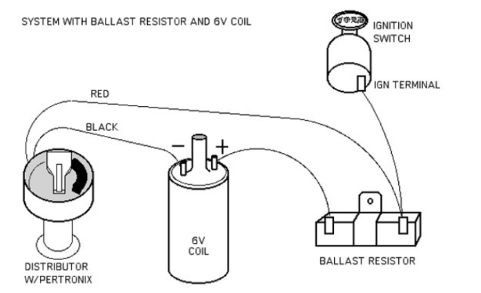
A typical ballast resistor wiring diagram will show the following connections:
- Battery positive (+) to the ignition switch.
- Ignition switch to the ballast resistor.
- Ballast resistor to the positive (+) terminal of the ignition coil.
- A separate wire from the starter solenoid (or the "start" position of the ignition switch) directly to the positive (+) terminal of the ignition coil, bypassing the ballast resistor. This provides a full 12v during cranking.
- Ignition coil negative (-) terminal to the distributor (points or electronic ignition module).
- Distributor to ground.
How It Works
Here's the breakdown of how the circuit functions:
When the ignition switch is in the "Run" position, power flows from the battery, through the ignition switch, through the ballast resistor, and finally to the positive (+) terminal of the ignition coil. The ballast resistor reduces the voltage to approximately 6-9 volts. This lower voltage is sufficient to keep the engine running and prevents the coil from overheating during prolonged operation. The negative (-) terminal of the coil is connected to the distributor. As the engine turns, the points (or electronic ignition module) in the distributor open and close, interrupting the current flow through the primary winding of the coil. This interruption causes the magnetic field in the coil to collapse rapidly, inducing a high-voltage surge in the secondary winding, which is then sent to the spark plugs via the distributor.
During cranking (when the ignition switch is in the "Start" position), a separate wire from the starter solenoid (or directly from the ignition switch) provides a full 12v to the coil, bypassing the ballast resistor. This ensures a strong spark for starting, as the battery voltage can drop significantly during cranking.
Real-World Use: Basic Troubleshooting
Here are some common issues and how to diagnose them using your understanding of the wiring diagram:
- No Spark:
- Check for 12v at the ignition coil (+) terminal with the ignition switch in the "Run" position. If no voltage, trace the wiring back through the ballast resistor and ignition switch to identify the break.
- Check the ballast resistor itself. A multimeter set to ohms should show a resistance value within the specified range (typically 0.8 to 2 ohms). An open circuit (infinite resistance) indicates a faulty resistor.
- Check the wire from the starter solenoid to the coil (+) terminal. This is only active during cranking, but a broken wire can prevent a strong starting spark.
- Inspect the distributor points (if applicable) for pitting, burning, or incorrect gap.
- Engine Runs, But Poorly: A faulty ballast resistor that's providing too much resistance can weaken the spark and cause poor performance.
- Coil Overheating: If the ballast resistor is bypassed or has failed in a way that allows full voltage to the coil continuously, the coil will overheat and eventually fail.
To diagnose these problems, you will need a multimeter. A multimeter allows you to check for voltage, current, and resistance in the circuit. You'll also need a basic understanding of how to use it. If you're not familiar with using a multimeter, watch some online tutorials or consult a repair manual.
Safety Precautions
Working with automotive electrical systems can be dangerous. Here are some essential safety tips:
- Disconnect the Battery: Always disconnect the negative (-) battery terminal before working on any electrical components. This prevents accidental shorts and potential shocks.
- Handle the Ignition Coil with Care: The ignition coil produces very high voltage. Avoid touching the spark plug wires or the coil terminals while the engine is running or being cranked.
- Be Mindful of Fuel Lines: Avoid creating sparks near fuel lines or fuel vapors.
- Use Proper Tools: Use insulated tools designed for automotive electrical work.
- Work in a Well-Ventilated Area: If you're working on the fuel system, work in a well-ventilated area to avoid inhaling fuel vapors.
The ignition coil itself can store a charge even after the engine is turned off. It's best to discharge the coil before handling it by grounding the high-voltage terminal (where the spark plug wire connects) to the chassis. Use an insulated screwdriver and wear gloves.
Diagram Download
That's the basics of the 12v ignition coil ballast resistor wiring diagram. Remember to consult your vehicle's specific wiring diagram for accurate wire colors and component locations. Having the correct diagram for your exact vehicle is crucial. I can provide a generic diagram, but it is much better for you to find the exact diagram to have the correct wire color code and wiring setup.
With this knowledge and a bit of careful work, you'll be well-equipped to tackle ignition system repairs and modifications with confidence.