
1965 Mustang Starter Solenoid Wiring Diagram
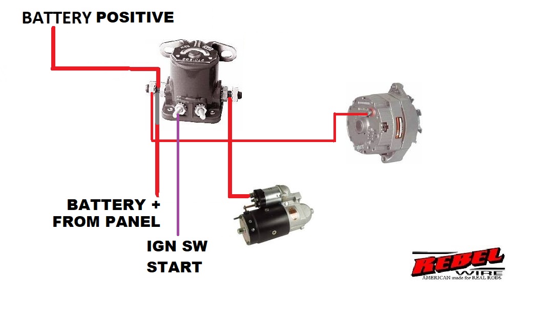
The 1965 Mustang, a classic American icon, often requires a deep understanding of its electrical system for proper maintenance and restoration. At the heart of that system, playing a critical role in starting the engine, is the starter solenoid. Understanding its wiring is crucial for diagnosing starting problems, performing repairs, or even upgrading your vintage Mustang's electrical components. This article serves as a detailed guide to interpreting the 1965 Mustang starter solenoid wiring diagram, equipping you with the knowledge to confidently tackle related issues.
Why Understanding the Wiring Diagram Matters
Whether you're restoring a barn find, performing routine maintenance, or upgrading your electrical system, understanding the starter solenoid wiring diagram provides several key benefits:
- Troubleshooting Starting Issues: A non-starting Mustang is a common problem. The wiring diagram helps pinpoint faults in the starting circuit, such as a faulty solenoid, damaged wires, or a bad ground.
- Performing Repairs: Accidents happen. Wires get cut, connectors corrode. Knowing the original wiring configuration is essential for making accurate and safe repairs.
- Upgrading the Electrical System: Installing a new starter, alternator, or even a complete wiring harness requires a clear understanding of the existing wiring to ensure compatibility and proper function.
- General Knowledge: Simply understanding how your car's systems work enhances your ability to maintain and appreciate your classic Mustang.
Key Specifications and Main Parts
Before diving into the diagram itself, it's important to understand the key components and their general specifications. Keep in mind that specifics may vary slightly depending on the exact production date and any modifications made over the years. However, the core principle remains the same.
- Starter Solenoid: This is an electromagnetic switch that connects the battery directly to the starter motor, allowing it to crank the engine. It’s usually mounted on the inner fender, close to the battery.
- Battery: The primary power source for the entire electrical system, including the starter. Typically a 12-volt battery.
- Starter Motor: This is the electric motor that physically turns the engine over.
- Ignition Switch: Controls the flow of electricity to various circuits when the key is turned.
- Neutral Safety Switch (Automatic Transmissions Only): This switch prevents the engine from starting unless the transmission is in Park or Neutral.
- Wiring: The conductors that carry electrical current between the various components. Wire gauge (thickness) is critical, with larger gauge wires needed for high-current applications like the starter circuit.
Decoding the Wiring Diagram: Symbols, Lines, and Colors
A wiring diagram is a symbolic representation of the electrical circuit. Understanding the symbols and conventions is key to interpreting the diagram effectively.
- Lines: Solid lines represent wires, indicating a direct electrical connection. Dashed lines may represent wires located within a harness or a protected enclosure.
- Colors: Wire colors are crucial for identification. Common colors include Red (power), Black (ground), Yellow, Blue, Green, and White. The diagram will usually have a color code legend.
- Symbols: Each component is represented by a specific symbol.
- Battery: Represented by a series of long and short parallel lines.
- Solenoid: Often shown as a coil with a switch.
- Starter Motor: A circle with an "M" inside.
- Ignition Switch: Represented by a switch symbol showing multiple positions (OFF, ACC, ON, START).
- Ground: Represented by a series of downward-pointing lines, sometimes resembling a Christmas tree.
- Numbers/Letters: Wires are often labeled with numbers or letters, corresponding to terminals or connectors.
Here's a breakdown of common color codes and their general meanings in a 1965 Mustang (though always confirm with your specific diagram):
- Red: Typically represents the main power feed from the battery.
- Black: Almost always represents ground.
- Yellow: Often used for circuits related to the ignition or starting system.
- Blue: Can vary, but often used for lighting or accessory circuits.
- Green: Often used for indicator lights or signals.
- White: Can be used for various circuits, including backup lights or neutral safety switch circuits.
How the Starter Solenoid Circuit Works
The starter solenoid circuit's operation can be broken down into the following steps:
- Key in the "START" Position: When you turn the ignition key to the "START" position, a small amount of current flows from the ignition switch.
- Activation Signal to Solenoid: This current travels to the small "S" terminal on the starter solenoid.
- Solenoid Activation: The current energizes the solenoid's internal coil, creating an electromagnetic field.
- Contact Closure: This electromagnetic field pulls a plunger that closes a heavy-duty switch inside the solenoid.
- Direct Battery Power to Starter: This closed switch connects the large positive (+) battery cable directly to the starter motor.
- Starter Engages: The starter motor receives a high surge of current, causing it to spin and engage the flywheel, cranking the engine.
- Key Release: When you release the key from the "START" position, the current to the solenoid is cut off, the switch opens, and the starter disengages.
In Mustangs with automatic transmissions, the neutral safety switch is wired in series with the ignition switch and the "S" terminal on the solenoid. This prevents the circuit from completing unless the transmission is in Park or Neutral.
Real-World Use: Basic Troubleshooting
Using the wiring diagram, you can diagnose common starter problems. Here are some basic troubleshooting steps:
- No Crank, No Click:
- Check the battery voltage. Is it at least 12.6 volts?
- Check the battery cable connections at the battery and solenoid. Are they clean and tight?
- Test the ignition switch. Is it sending power to the "S" terminal of the solenoid when in the "START" position? Use a multimeter to check for voltage.
- No Crank, Click Sound:
- This usually indicates a problem with the starter motor itself, the solenoid contacts, or the high-current battery cables.
- Check the voltage at the starter motor while attempting to start the car. If voltage is present but the starter doesn't turn, the starter motor is likely faulty.
- Inspect the large battery cables for corrosion or damage.
- Starter Cranks Slowly:
- This often indicates a weak battery, poor battery cable connections, or a failing starter motor.
- Perform a voltage drop test across the battery cables to check for excessive resistance.
Important Note: When troubleshooting, always disconnect the negative battery cable to prevent accidental short circuits.
Safety Precautions
Working with automotive electrical systems can be dangerous. Here are some critical safety precautions:
- Disconnect the Battery: Always disconnect the negative battery cable before working on the electrical system to prevent short circuits and potential shocks.
- Work in a Well-Ventilated Area: Batteries can produce explosive gases. Work in a well-ventilated area to avoid potential explosions.
- Wear Safety Glasses: Protect your eyes from sparks and debris.
- Use Proper Tools: Use insulated tools designed for automotive electrical work.
- Be Aware of High-Current Components: The starter circuit carries a very high current. Avoid short-circuiting the battery or starter motor, as this can cause severe burns or damage to the electrical system. The large battery cables are especially risky!
Remember to consult your specific 1965 Mustang's shop manual for detailed procedures and specifications. The information provided here is a general guide and should not replace the expertise of a qualified mechanic.
I have access to a printable version of the 1965 Mustang Starter Solenoid Wiring Diagram. If you'd like a copy, just let me know, and I can make it available for download.