1965 Mustang Wiring Diagrams Electrical Schematics
The 1965 Ford Mustang. A true icon of American automotive history. Whether you're restoring one, modifying it for performance, or just trying to keep it running reliably, understanding its electrical system is crucial. And the key to that understanding? The wiring diagram, also known as an electrical schematic. This article will guide you through the intricacies of the 1965 Mustang wiring diagram, equipping you with the knowledge to confidently tackle electrical projects.
Purpose of the 1965 Mustang Wiring Diagram
Why bother with a wiring diagram? The simple answer is: everything. These diagrams are indispensable for:
- Troubleshooting Electrical Problems: Identifying shorts, opens, and other faults within the system. Without a map, you're just poking around in the dark.
- Restoration Projects: Ensuring correct wiring placement during a complete rebuild. Originals are often brittle, damaged, or simply missing.
- Modifications and Upgrades: Safely integrating new components like modern stereos, fuel injection systems, or aftermarket lighting. You need to know where to tap in and what to avoid.
- Learning the System: Gaining a deeper understanding of how the various electrical components interact. This empowers you to diagnose and repair issues more effectively.
Think of the wiring diagram as the blueprint for your Mustang's electrical nervous system. It shows how all the components are connected and how electricity flows through the car. Knowing how to read and interpret this blueprint is essential for anyone working on a classic Mustang.
Key Specs and Main Electrical Parts
Before diving into the diagram itself, let's familiarize ourselves with some key specifications and the main electrical components you'll encounter:
- Voltage: 12V DC (Direct Current) – The standard automotive voltage of the time.
- Battery: Provides the initial electrical power to start the engine and operate accessories. Typically located in the engine bay.
- Alternator (Generator): Recharges the battery and provides power to the electrical system while the engine is running. Driven by a belt connected to the engine.
- Starter Motor: Cranks the engine to initiate combustion. A high-current device requiring thick wiring.
- Ignition System: Includes the ignition coil, distributor, points (or electronic ignition), and spark plugs. Responsible for igniting the air-fuel mixture in the cylinders.
- Lighting System: Headlights, taillights, turn signals, brake lights, parking lights, and interior lights.
- Gauges: Fuel gauge, temperature gauge, oil pressure gauge, and ammeter (or voltmeter). Provide information about the engine's operating conditions.
- Fuses and Circuit Breakers: Protective devices that interrupt the flow of electricity in case of a short circuit or overload. Located in the fuse box.
- Wiring Harness: A bundle of wires that connects all the electrical components together.
- Switches: Control the flow of electricity to various circuits. Examples include the ignition switch, headlight switch, and turn signal switch.
- Relays: Electrically operated switches that allow a low-current circuit to control a high-current circuit. Used for headlights, starter motor, and other high-power devices.
Understanding the Symbols and Colors
The 1965 Mustang wiring diagram uses a standardized set of symbols and color codes to represent different components and wiring functions. Learning these is fundamental to interpreting the diagram correctly.
Lines:
- Solid Lines: Represent wires. The thickness of the line may, but doesn't always, indicate the wire gauge (thickness).
- Dashed Lines: Can indicate shielded wires or ground connections. Always refer to the legend on the diagram itself, as conventions can vary.
- Lines Crossing: Where lines cross without a dot, it means the wires are not electrically connected.
- Lines with a Dot: Where lines cross with a dot, it means the wires are electrically connected. This is called a splice.
Colors:
Wire colors are extremely important. They help you identify the function of each wire. Common colors include:
- Red: Typically used for power wires connected directly to the battery or ignition switch.
- Black: Usually represents ground connections.
- Blue: Often used for lighting circuits.
- Yellow: Commonly used for ignition circuits.
- Green: Often used for turn signals and brake lights.
- White: Frequently used for gauges and other sensors.
Important Note: While these are general guidelines, the exact color coding can vary slightly depending on the specific model and year of the Mustang. Always refer to the wiring diagram for your specific vehicle.
Icons:
The diagram uses icons to represent various electrical components. Some common icons include:
- Battery: A series of alternating long and short lines.
- Resistor: A zigzag line.
- Capacitor: Two parallel lines.
- Coil: A spiral or coil-shaped symbol.
- Switch: A line that can be opened or closed to complete or break a circuit.
- Fuse: A small rectangle with a wavy line inside.
- Ground: A series of lines that get shorter towards the bottom, resembling an inverted triangle.
- Light Bulb: A circle with an 'X' inside.
- Motor: A circle with an 'M' inside.
Most diagrams include a key or legend that defines all the symbols used. Take the time to study this legend before attempting to interpret the diagram.
How It Works: Following the Circuit
Understanding how the electrical system works requires tracing the flow of electricity through the various circuits. Start with the battery, which provides the initial power. From there, follow the wires through switches, fuses, relays, and finally to the component you're interested in (e.g., a headlight, the starter motor). Pay close attention to the color coding and the symbols used to represent each component.
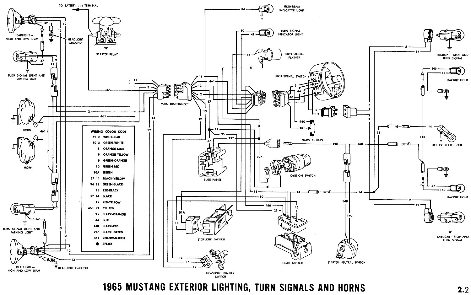
For example, let's trace the headlight circuit. You'll see a wire running from the battery (or a power distribution point) to the headlight switch. When you turn on the headlight switch, it completes the circuit, allowing electricity to flow through the wires to the headlights, causing them to illuminate. A fuse is typically placed in this circuit to protect it from overloads.
Real-World Use: Basic Troubleshooting Tips
The wiring diagram is your best friend when troubleshooting electrical problems. Here are some basic troubleshooting tips:
- Start with the Basics: Check the battery voltage, fuses, and ground connections. A weak battery or a blown fuse can cause a wide range of problems.
- Use a Multimeter: A multimeter is an essential tool for measuring voltage, current, and resistance. Use it to check for voltage at various points in the circuit and to test for continuity (a complete circuit).
- Identify the Affected Circuit: Determine which circuit is causing the problem. For example, if the headlights aren't working, focus on the headlight circuit.
- Isolate the Problem: Disconnect components one by one to isolate the source of the problem. For example, if you suspect a short circuit in a headlight, disconnect the headlight and see if the short disappears.
- Check for Opens and Shorts: Use a multimeter to check for opens (breaks in the circuit) and shorts (unintended connections to ground).
For example, if your turn signals aren't working, consult the wiring diagram to locate the turn signal circuit. Check the fuse, the turn signal switch, and the wiring to the turn signal bulbs. Use a multimeter to check for voltage at the switch and the bulbs. If you find a broken wire or a faulty switch, replace it.
Safety First!
Working with electrical systems can be dangerous. Always take the following safety precautions:
- Disconnect the Battery: Before working on any electrical component, disconnect the negative battery cable to prevent accidental shocks.
- Use Insulated Tools: Use tools with insulated handles to protect yourself from electric shock.
- Avoid Working in Wet Conditions: Water conducts electricity, so avoid working on electrical systems in wet conditions.
- Be Careful with High-Current Circuits: Circuits like the starter motor circuit and the alternator circuit carry high currents, which can be dangerous. Be extra careful when working on these circuits. The alternator, specifically, can deliver a powerful shock even with the battery disconnected due to residual magnetism. Exercise caution.
- Never Bypass Fuses: Fuses are there to protect the electrical system from overloads. Never bypass a fuse with a wire or a higher amperage fuse. This can cause a fire.
Remember, safety is paramount. If you are not comfortable working on electrical systems, consult a qualified mechanic.
With careful study and practice, you'll be able to confidently navigate the 1965 Mustang wiring diagram and tackle electrical repairs and modifications with ease. The knowledge and skills you gain will be invaluable for maintaining and restoring your classic Mustang.
We have the complete 1965 Mustang wiring diagram available for download. Contact us, and we'll gladly provide it to you.