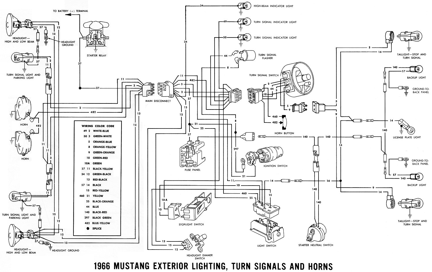
1966 Mustang Wiring Diagrams Electrical Schematics
Let's dive into the electrical heart of your classic 1966 Mustang. Understanding the wiring diagram isn't just about fixing a blown fuse; it's about truly understanding your car, enabling you to perform modifications, upgrades, and even diagnose complex electrical issues with confidence. This article aims to provide you with the knowledge needed to decipher and utilize the 1966 Mustang wiring diagram like a seasoned mechanic.
Purpose: Why a Wiring Diagram is Your Best Friend
The wiring diagram, also known as an electrical schematic, is the roadmap of your car's electrical system. It shows how all the electrical components are connected, allowing you to:
- Troubleshoot Problems: Pinpoint the source of electrical malfunctions quickly and accurately. Instead of blindly replacing parts, you can trace the circuit to find the fault.
- Perform Repairs: Execute repairs correctly, ensuring that new wiring matches the original specifications and connections.
- Install Accessories: Integrate aftermarket accessories like stereos, alarms, or upgraded lighting systems safely and effectively.
- Understand Your Car: Gain a deeper understanding of how the various electrical systems function, allowing you to maintain your Mustang proactively.
- Restore or Modify: Crucial when restoring a classic Mustang or performing custom modifications.
Key Specs and Main Parts of the 1966 Mustang Electrical System
The 1966 Mustang electrical system is relatively straightforward compared to modern vehicles, but it still encompasses numerous circuits and components. Key areas include:
- Battery: Typically a 12-volt lead-acid battery, providing the primary power source.
- Alternator (or Generator): Charges the battery and supplies power when the engine is running. The '66 Mustang could come with either a generator (early models) or an alternator (later models). Understanding which you have is vital, as their wiring differs slightly.
- Starter Motor: Cranks the engine to initiate combustion.
- Ignition System: Includes the ignition coil, distributor, points (or electronic ignition if upgraded), and spark plugs.
- Lighting System: Headlights, taillights, parking lights, turn signals, and interior lights.
- Wiring Harness: The network of wires that connects all the electrical components.
- Fuses: Safety devices that protect circuits from overcurrent. These are located in the fuse box.
- Switches: Controls for various electrical functions (e.g., headlight switch, ignition switch, turn signal switch).
- Grounds: Essential for completing circuits. Poor grounding is a common cause of electrical problems.
The amperage rating for each circuit is critical. Overloading a circuit can melt wires and cause fires. The wiring diagram will typically indicate the correct fuse amperage for each circuit.
Decoding the Symbols: Lines, Colors, and Icons
Understanding the symbols used in the wiring diagram is essential for interpreting it correctly. Here's a breakdown:
- Lines: Represent wires. The thickness of the line doesn't necessarily indicate wire gauge, but it might be used to differentiate between main power feeds and smaller signal wires in some diagrams.
- Colors: Each wire has a specific color code, which is usually indicated on the diagram (e.g., RED, BLK, GRN). This is crucial for tracing wires in the actual car. The color codes often use abbreviations.
- Icons: Represent electrical components. Common icons include:
- Resistor: Zigzag line.
- Capacitor: Two parallel lines.
- Coil: A series of loops.
- Switch: A line that can be connected or disconnected from another line.
- Fuse: A line with a break in the middle, often with an "F" or amperage rating nearby.
- Ground: A series of lines, typically resembling an inverted pyramid.
- Light Bulb: A circle with an "X" inside.
- Motor: A circle with an "M" inside.
- Diode: A triangle pointing to a line.
Pay close attention to the *junctions* where wires connect. These are often indicated by a dot where lines intersect. If there's no dot, the wires are simply crossing paths without connecting.
How It Works: Tracing a Circuit
The wiring diagram shows the flow of electricity from the battery, through various components, and back to ground. To trace a circuit, start at the power source (e.g., the battery or alternator) and follow the line representing the wire through the circuit. For example, let's imagine you're tracing the circuit for the headlights:
- Start at the battery (positive terminal).
- Follow the line to the ignition switch or a dedicated headlight relay (depending on the specific circuit configuration).
- From the switch, the line continues to the headlight switch.
- From the headlight switch, the lines split and go to each headlight.
- Each headlight has a wire going to ground.
By following the lines and understanding the components in the circuit, you can understand how the headlights are powered and controlled.
Real-World Use: Basic Troubleshooting Tips
Here are some basic troubleshooting tips using the wiring diagram:
- No Power: If a circuit isn't working, start by checking the fuse. The wiring diagram will tell you which fuse protects that circuit. If the fuse is blown, replace it with one of the correct amperage rating. If it blows again immediately, there's a short circuit somewhere in the wiring. Use the diagram to trace the circuit and look for damaged wires or components.
- Short Circuit: A short circuit occurs when a wire comes into direct contact with ground, bypassing the intended load (e.g., a light bulb). This causes excessive current flow and blows the fuse. Look for frayed insulation or wires that are touching metal.
- Open Circuit: An open circuit occurs when there's a break in the wiring, preventing current from flowing. This could be caused by a broken wire, a loose connection, or a faulty switch. Use a multimeter to check for continuity along the circuit.
- Grounding Issues: Poor grounding can cause a variety of electrical problems, including dim lights, erratic operation, and even blown fuses. Make sure all ground connections are clean and tight. The wiring diagram will show the location of all ground points.
When troubleshooting, it's helpful to divide the circuit into sections and test each section individually. This will help you isolate the fault more quickly.
Safety First: Highlighting Risky Components
Working with automotive electrical systems can be dangerous if you don't take proper precautions:
- Battery: Always disconnect the negative battery cable before working on the electrical system. This will prevent accidental short circuits.
- High-Voltage Components: The ignition system contains high-voltage components that can deliver a painful (and potentially dangerous) shock. Avoid touching the ignition coil, distributor, or spark plug wires while the engine is running or the ignition is turned on.
- Airbag Systems: If your Mustang has an airbag system (though unlikely for a '66 unless modified), be extremely careful when working near the airbag control unit or sensors. Accidental deployment of an airbag can cause serious injury. Consult a qualified technician before working on airbag systems.
- Fuel System: The fuel pump and fuel injectors are part of the electrical system and are located near flammable fuel. Avoid creating sparks or using open flames in this area.
Always use appropriate tools and safety equipment, such as insulated pliers, screwdrivers, and safety glasses. If you're not comfortable working on the electrical system, consult a qualified mechanic.
Important: Always double-check the wiring diagram against your specific Mustang. There can be variations based on the model year, options, and any previous modifications.
With a little patience and practice, you can learn to read and use the 1966 Mustang wiring diagram effectively. It's a valuable tool that will empower you to maintain, repair, and upgrade your classic Mustang with confidence.
We have the complete, high-resolution 1966 Mustang wiring diagram available for download. You'll find it invaluable for your projects.