1968 Ford Mustang Electrical Wiring Diagram
The 1968 Ford Mustang. A classic. Whether you're restoring one, adding aftermarket accessories, or simply trying to diagnose an electrical issue, a solid understanding of its wiring is paramount. And that's where the 1968 Ford Mustang electrical wiring diagram comes in. This article provides a detailed guide to help you navigate this crucial resource.
Purpose of the Wiring Diagram
Why is this diagram so vital? Simple. It’s the roadmap to your Mustang's entire electrical system. Think of it as the Rosetta Stone for circuits. Without it, you're essentially poking around in the dark. Specifically, the diagram serves several key purposes:
- Troubleshooting: Pinpointing shorts, opens, and other electrical faults becomes significantly easier when you can trace the circuit's path.
- Repairing: Correctly rewiring damaged sections, replacing components, and ensuring proper connections are achievable with accurate guidance.
- Modification: Adding aftermarket accessories (stereos, lights, etc.) can be done safely and effectively when you understand the existing wiring and how to integrate new components.
- Restoration: Ensuring correct wiring during a restoration project is critical for authenticity and functionality.
- Learning: Simply understanding how the electrical system works enhances your overall knowledge of automotive technology.
Key Specs and Main Parts
Before diving into the diagram itself, let's cover some fundamental aspects of the 1968 Mustang's electrical system:
- Voltage: Primarily 12V DC (Direct Current). Knowing this is essential when diagnosing voltage drops or using testing equipment.
- Battery: Typically a Group 24 or 24F lead-acid battery.
- Alternator: Generates the 12V to charge the battery and power the electrical system when the engine is running.
- Starter: Cranks the engine for starting. A high-current device.
- Ignition System: Consists of the ignition coil, distributor, points (in standard ignition), condenser, and spark plugs.
- Lighting System: Headlights, taillights, turn signals, brake lights, and interior lights.
- Wiring Harness: The central nervous system of the electrical system. A collection of wires bundled together and routed throughout the car.
- Fuses: Protective devices that interrupt the circuit when excessive current flows, preventing damage to components. Understanding the fuse box layout and amperage ratings is crucial.
- Relays: Electrically operated switches used to control high-current circuits with a low-current signal (e.g., headlight relay).
- Grounds: Essential for completing the circuit. Poor grounds are a common source of electrical problems.
Understanding the Symbols
The wiring diagram is a symbolic language. Here's how to decipher it:
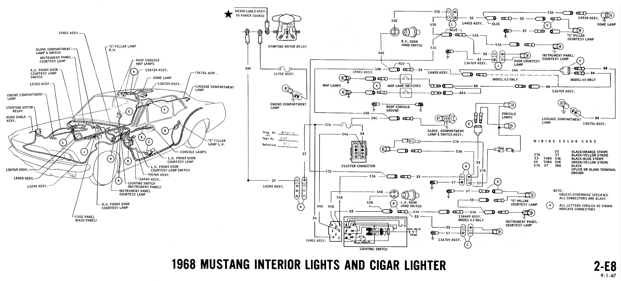
Lines and Colors
Lines represent wires. The thickness often indicates the wire's gauge (thicker lines for higher current). Colors are critical for identifying specific wires in the harness. Common colors include:
- Red: Typically power from the battery.
- Black: Typically ground.
- Blue: Often used for lighting circuits.
- Yellow: Sometimes used for ignition or charging circuits.
- Green: Often used for turn signals or other indicator lights.
The diagram usually includes a color code key, so always refer to it for accurate identification. Dashed lines may indicate wires hidden within a harness or between components.
Icons
Icons represent electrical components. Here are some common ones:
- Battery: A series of short and long parallel lines.
- Fuse: A zigzag line within a rectangle.
- Resistor: A zigzag line.
- Coil (e.g., Ignition Coil): A series of looped lines.
- Ground: A series of downward-pointing triangles.
- Switch: A line that can be open or closed to complete a circuit.
- Light Bulb: A circle with a filament inside.
- Diode: A triangle pointing to a line.
- Relay: A coil and a switch, often shown separately but linked by a dashed line indicating the coil controls the switch.
Splices
Splices are points where wires connect. They're usually indicated by a dot where lines intersect. The diagram will sometimes designate where splices are located, which is helpful when tracking down issues in the harness.
How It Works: Following a Circuit
Let’s trace a simplified circuit, the headlight circuit, to illustrate how to use the diagram. Imagine you have the diagram in front of you.
- Start at the Power Source: Find the battery symbol. A red wire (usually) will lead from the battery to the starter solenoid.
- Trace the Path: From the solenoid, another wire (likely red or another color) will lead to the headlight switch.
- Through the Switch: The headlight switch controls the flow of current to the headlights. When the switch is on, it completes the circuit.
- To the Headlights: Wires (likely blue or yellow) will run from the headlight switch to each headlight.
- Ground: Each headlight will have a ground wire (usually black) connected to the car's chassis, completing the circuit.
By following this path on the diagram, you can see how each component is connected and understand the flow of electricity. Remember to pay attention to wire colors and gauge.
Real-World Use: Basic Troubleshooting
Here are some basic troubleshooting tips using the wiring diagram:
- No Headlights: Use the diagram to check the fuse, headlight switch, and wiring to the headlights. Use a multimeter to test for voltage at each point.
- Turn Signals Not Working: Check the flasher unit, turn signal switch, and wiring to the turn signal lights.
- Battery Draining: Identify potential parasitic draws by systematically disconnecting circuits and monitoring the battery drain. The diagram helps you identify which circuits to isolate.
- Component Replacement: Before replacing any component, use the diagram to verify the wiring connections and ensure you're connecting the replacement correctly.
Safety Precautions
Working with automotive electrical systems can be dangerous. Always disconnect the negative battery cable before working on the electrical system to prevent shorts and potential fires.
Be particularly careful when working with the following:
- Battery: Contains corrosive acid and can produce explosive gases.
- Alternator: Can produce high voltages and currents.
- Ignition System: Can produce high voltages that can be lethal.
- Any circuit with a fuse: If a fuse blows repeatedly, it indicates a short circuit or overload. Don't simply replace the fuse with a higher amperage one; find and fix the underlying problem.
Always use the appropriate safety equipment, including eye protection and gloves. When in doubt, consult a qualified electrician.
Remember, electricity doesn't discriminate; it will follow the path of least resistance, and that could be through you if you're not careful.
With this information, you're now well-equipped to tackle the 1968 Ford Mustang electrical wiring diagram. Understanding this diagram is a critical skill for any Mustang enthusiast, allowing for effective troubleshooting, repair, and modification. Good luck, and happy wiring!