
1969 Ford F100 Ignition Wiring Diagram
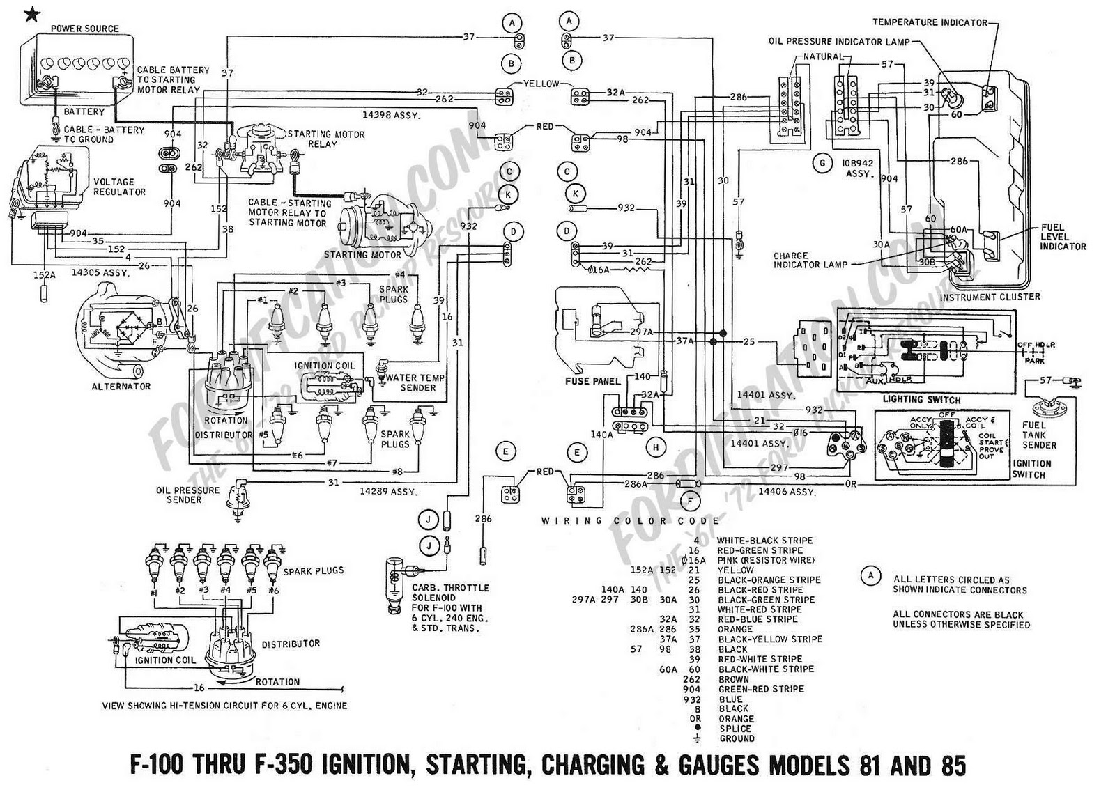
The 1969 Ford F100 is a classic truck, beloved for its ruggedness and straightforward design. However, even the most dependable vehicles require maintenance and repairs, and the electrical system is often a source of headaches. Having a clear understanding of the ignition wiring is crucial for troubleshooting issues, performing upgrades, or even just gaining a better appreciation for how your truck works. This article will dissect the 1969 Ford F100 ignition wiring diagram, providing you with the knowledge to confidently tackle electrical tasks.
Purpose of the Ignition Wiring Diagram
Why bother understanding this diagram? Several reasons:
- Troubleshooting Electrical Problems: When your truck won't start, sputters, or experiences intermittent electrical issues, the wiring diagram becomes your roadmap. It allows you to trace circuits, identify faulty components, and pinpoint the exact location of the problem.
- Performing Repairs and Replacements: Whether you're replacing a worn-out ignition switch, distributor, or coil, the diagram ensures you connect the components correctly, preventing further damage and ensuring proper operation.
- Making Modifications and Upgrades: If you're upgrading to an electronic ignition system, installing aftermarket gauges, or adding new electrical accessories, the diagram helps you integrate these components safely and effectively into the existing wiring harness.
- Gaining a Deeper Understanding: Simply put, studying the diagram increases your knowledge of your truck's inner workings and builds confidence when tackling any electrical task.
Key Specs and Main Parts of the 1969 F100 Ignition System
The 1969 Ford F100, depending on the engine, typically used a points-based ignition system. Here are the key components:
- Battery: The heart of the electrical system, providing the necessary voltage (typically 12V DC) to power all components.
- Ignition Switch: A multi-position switch that controls the flow of power to the ignition system, starter solenoid, and other accessories. Key positions usually include: OFF, ACC (Accessory), ON (Run), and START.
- Ballast Resistor (or Resistor Wire): This resistor, often a length of special resistance wire, reduces the voltage supplied to the ignition coil during normal operation. This protects the points from burning out prematurely. During cranking (START position), the ballast resistor is often bypassed to provide the coil with a full 12 volts for a stronger spark.
- Ignition Coil: A transformer that steps up the relatively low voltage from the battery (around 12 volts) to a much higher voltage (15,000-25,000 volts or more) needed to create a spark at the spark plugs.
- Distributor: A mechanical device that contains the points, condenser, and rotor. It performs two key functions:
- Timing: It opens and closes the points at precisely timed intervals, triggering the ignition coil to discharge.
- Distribution: It distributes the high-voltage spark from the coil to the correct spark plug at the correct time in the engine's firing order.
- Points (Contact Points): A set of contacts within the distributor that open and close, completing and interrupting the primary circuit of the ignition coil. The "dwell" angle is the number of degrees of distributor rotation that the points remain closed.
- Condenser (Capacitor): A small capacitor connected in parallel with the points. It absorbs the back EMF (electromotive force) generated when the points open, preventing arcing across the points and prolonging their life.
- Rotor: A rotating arm inside the distributor that distributes the high-voltage spark to the spark plug wires.
- Spark Plug Wires (High-Tension Leads): Thick, insulated wires that carry the high-voltage spark from the distributor to the spark plugs.
- Spark Plugs: Devices screwed into the cylinder head that ignite the air-fuel mixture in the combustion chamber, initiating the power stroke.
- Starter Solenoid: An electromagnetic switch that engages the starter motor and allows high current to flow to it from the battery. It’s usually mounted on the fender or starter itself.
- Starter Motor: An electric motor that cranks the engine, allowing it to start.
Understanding the Symbols in the Wiring Diagram
Wiring diagrams use a standardized set of symbols to represent electrical components and connections. Here's a breakdown of the common symbols you'll encounter in a 1969 F100 ignition wiring diagram:
- Solid Lines: Represent wires. The thickness of the line may, but doesn't always, indicate wire gauge (thicker lines for higher current).
- Dashed Lines: Often represent wires or connections that are part of a sub-system or optional circuit.
- Circles: Can represent various components, depending on what's inside. A circle with a 'B' typically represents the battery, while other circles with symbols inside might represent relays, fuses, or other electrical devices.
- Rectangles: Commonly represent switches, such as the ignition switch.
- Zigzag Line: Usually represents a resistor. The ballast resistor will often be depicted this way.
- Ground Symbol: A symbol resembling an inverted Christmas tree or stacked horizontal lines, indicating a connection to the vehicle's chassis, which serves as the ground (negative) return path for the electrical system.
- Wire Colors: Wiring diagrams use standardized color codes to identify each wire. Key colors include:
- Red: Typically indicates a power wire coming directly from the battery.
- Black: Indicates a ground wire.
- Yellow: Often used for switched power or accessory circuits.
- Blue: Can be used for various circuits, often related to lighting or signaling.
- Green: Often used for grounds or sensor signals.
How the 1969 F100 Ignition System Works
Here's a simplified explanation of how the ignition system works:
- Power from the Battery: When the ignition switch is turned to the ON position, power flows from the battery, through the ignition switch, and to the ballast resistor (or resistor wire).
- Voltage Reduction: The ballast resistor reduces the voltage to around 6-9 volts (depending on the specific resistor) before it reaches the ignition coil.
- Coil Primary Circuit: The reduced voltage powers the primary winding of the ignition coil. The other side of the coil primary winding is connected to the points in the distributor.
- Points Open and Close: As the engine rotates, the distributor cam opens and closes the points. When the points are closed, the primary circuit of the ignition coil is completed, and current flows through the coil's primary winding, creating a magnetic field.
- Coil Secondary Circuit: When the points open, the primary circuit is interrupted, causing the magnetic field to collapse rapidly. This rapid collapse induces a high voltage in the coil's secondary winding.
- Spark Distribution: The high-voltage spark travels from the coil to the distributor cap, where the rotor directs it to the appropriate spark plug wire.
- Spark Plug Ignition: The high-voltage spark jumps the gap at the spark plug, igniting the air-fuel mixture in the cylinder, initiating the power stroke.
- Starting the Engine: When the ignition switch is turned to the START position, the starter solenoid is energized, engaging the starter motor and cranking the engine. Simultaneously, the ballast resistor is often bypassed, providing full battery voltage to the coil for a stronger spark during starting.
Real-World Use: Basic Troubleshooting Tips
Using the wiring diagram, you can diagnose common ignition problems:
- No Spark: If there's no spark at the spark plugs, check the following:
- Battery Voltage: Ensure the battery is fully charged.
- Ignition Switch: Test for voltage at the ignition coil with the switch in the ON position.
- Ballast Resistor: Check the ballast resistor for continuity. A failed resistor will prevent voltage from reaching the coil.
- Coil: Test the coil for proper resistance in both the primary and secondary windings.
- Points: Inspect the points for pitting, burning, or improper gap. Clean or replace as needed.
- Condenser: A faulty condenser can cause weak spark or no spark.
- Distributor Cap and Rotor: Check for cracks, carbon tracking, or corrosion.
- Spark Plug Wires: Test the resistance of each spark plug wire. Excessive resistance indicates a faulty wire.
- Weak Spark: A weak spark can cause misfires and poor engine performance. Possible causes include:
- Low Battery Voltage
- Faulty Ignition Coil
- Worn Points
- Incorrect Point Gap or Dwell
- Faulty Condenser
- Engine Cranks But Won't Start: Check if the coil is getting power while cranking. If not, the issue could be with the starter solenoid bypassing circuit or a faulty ignition switch.
Safety Precautions
Working with the electrical system involves risk! Here are some important safety precautions:
- Disconnect the Battery: Always disconnect the negative battery cable before working on any electrical components. This prevents accidental shorts and electrical shocks.
- High Voltage: Be extremely careful when working around the ignition coil and spark plug wires. These components carry extremely high voltage, which can be lethal. Never touch these components while the engine is running or being cranked.
- Use Proper Tools: Use insulated tools to prevent accidental shorts.
- Double-Check Connections: Ensure all connections are clean and secure. Loose or corroded connections can cause electrical problems and even fires.
- Consult a Professional: If you're unsure about any aspect of the electrical system, consult a qualified mechanic.
By understanding the 1969 Ford F100 ignition wiring diagram and following these safety precautions, you can confidently diagnose and repair electrical issues, keeping your classic truck running smoothly for years to come. Remember to always double-check your work and consult a professional if you are unsure about any aspect of the repair.
We have a high-resolution version of the 1969 Ford F100 ignition wiring diagram available for download. This will be invaluable for your repair and modification projects. Contact us for the file.