1969 Mustang Ignition Switch Wiring Diagram
Understanding the ignition switch wiring diagram for a 1969 Mustang is crucial for various reasons, ranging from simple repairs and component replacement to more complex modifications and diagnosing electrical problems. This article will provide an in-depth look at the diagram, explaining its symbols, components, and functionality, allowing you to troubleshoot and maintain your classic Mustang's electrical system with confidence.
Why This Diagram Matters
The 1969 Mustang's ignition switch is a central point for the car's electrical system. Knowing its wiring allows you to:
- Diagnose Starting Problems: Is your car not starting? The ignition switch is a prime suspect.
- Replace a Faulty Switch: Swapping out a worn or broken switch requires accurate wiring knowledge.
- Troubleshoot Electrical Issues: Problems with the lights, radio, or other accessories can sometimes be traced back to the ignition switch.
- Install Aftermarket Accessories: Adding new components often requires tapping into the car's electrical system, and the ignition switch is a convenient point.
- Restore Originality: Ensuring correct wiring is essential for maintaining the authenticity of your classic Mustang.
Key Specs and Main Parts
The 1969 Mustang ignition switch is a multi-position switch with several terminals. Here are the key components you'll encounter in the wiring diagram:
- Battery (BAT): The main power source for the car's electrical system. Typically a thick red wire connected to the starter solenoid.
- Ignition (IGN): Powers the ignition system, including the coil, distributor, and ignition module (if equipped). Powers the engine only when running.
- Accessory (ACC): Powers accessories like the radio, heater, and wipers. This circuit is active when the key is in the ACC or RUN positions.
- Starter (STR or SOL): Activates the starter solenoid, which engages the starter motor to crank the engine. Only powered when the key is in the START position.
- Ground (GND): A return path for current flow, connected to the car's chassis. Although the ignition switch itself might not be directly grounded, it's essential to understand the grounding system in the car.
It's crucial to note that some models may have slight variations in wiring depending on options and sub-models. Always consult the specific diagram for your vehicle for the most accurate information.
Decoding the Symbols
Understanding the symbols in the wiring diagram is paramount for interpreting it correctly. Here are some common symbols and conventions you'll encounter:
- Lines: Solid lines represent wires, indicating the path of electrical current. Dashed lines may represent a shared ground or a connector.
- Colors: Wires are color-coded to identify their function. Common colors in a 1969 Mustang include:
- Red: Typically indicates a power wire, often connected to the battery.
- Black: Usually represents ground.
- Yellow: Commonly used for circuits like the starter solenoid or ignition.
- Blue: Often used for accessories or lighting circuits.
- Green: Can indicate turn signals, brake lights, or other specific functions.
- Circles or Squares: These represent terminals or connection points.
- Numbers or Letters: These are often used to identify specific terminals or wires within a circuit.
- Component Symbols: Simple drawings represent components like the ignition switch itself, the starter solenoid, and the battery.
The diagram will often show the wires going to and from the ignition switch in a simplified representation. You'll see lines connecting the switch to other components, with labels indicating the wire color and gauge (thickness).
How It Works: A Simplified Explanation
The ignition switch is essentially a rotary switch with multiple positions. Each position connects different terminals, enabling specific circuits.
- OFF: No circuits are connected. The car is completely off.
- ACC (Accessory): The BAT terminal connects to the ACC terminal, powering accessories like the radio and heater. The engine is not running.
- RUN (Ignition): The BAT terminal connects to both the ACC and IGN terminals. Accessories are powered, and the ignition system is activated, allowing the engine to run.
- START: The BAT terminal connects to the ACC, IGN, and STR terminals. The starter motor is engaged to crank the engine. Once the engine starts, the key is released to the RUN position.
The internal mechanism of the switch uses metal contacts that slide against each other as the key is turned. These contacts can wear out over time, leading to intermittent electrical problems.
Real-World Use: Basic Troubleshooting
Here are some common problems and troubleshooting tips using the ignition switch wiring diagram:
- Car Won't Start (No Crank):
- Check the battery voltage.
- Verify that the starter solenoid is receiving power when the key is in the START position. Use a multimeter to check voltage at the STR terminal of the ignition switch and the starter solenoid.
- If there's no voltage at the STR terminal, the ignition switch may be faulty.
- Car Starts But Dies Immediately:
- The IGN circuit may be failing. Check for voltage at the IGN terminal of the ignition switch in the RUN position.
- Inspect the wiring between the ignition switch and the coil or ignition module.
- Accessories Not Working:
- Check the fuse for the accessory circuit.
- Verify that the ACC terminal of the ignition switch is receiving power when the key is in the ACC or RUN positions.
Important: Always disconnect the battery's negative terminal before working on any electrical components to prevent short circuits and potential damage.
Safety Considerations
Working with automotive electrical systems can be dangerous. Here are some safety precautions to keep in mind:
- Disconnect the Battery: As mentioned before, always disconnect the battery's negative terminal before working on any electrical components.
- Use a Multimeter: A multimeter is essential for diagnosing electrical problems. Learn how to use it correctly to measure voltage, current, and resistance.
- Avoid Short Circuits: Be careful not to create short circuits by accidentally grounding live wires.
- Work in a Well-Ventilated Area: Battery acid and other chemicals can release harmful fumes.
- Don't Work Alone: It's always a good idea to have someone nearby in case of an emergency.
- The Starter Solenoid: This component carries high amperage and can cause burns or electrical shock if not handled carefully. Always disconnect the battery before working on the starter or solenoid.
Wrapping Up
The 1969 Mustang ignition switch wiring diagram is an invaluable tool for maintaining and repairing your classic car. By understanding the symbols, components, and functionality of the diagram, you can confidently diagnose and resolve electrical problems. Remember to always prioritize safety and consult the specific diagram for your vehicle's year and model to ensure accuracy.
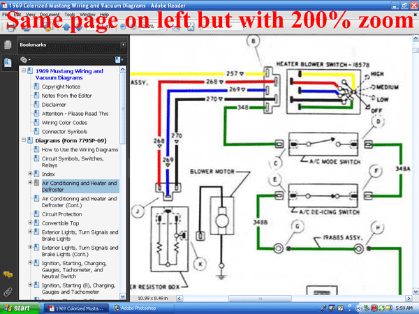
We have the full, high-resolution diagram available for download. This will allow you to zoom in on specific sections and see the details more clearly. With this diagram and the knowledge you've gained in this article, you'll be well-equipped to tackle any ignition switch-related issues on your 1969 Mustang.