1973 Eldorado Anti Lock Brake System Diagram
Welcome to a deep dive into the fascinating world of early automotive technology! Today, we're cracking open the 1973 Cadillac Eldorado's Anti-Lock Brake System (ABS) diagram. This system, while primitive by modern standards, was a groundbreaking innovation. Understanding its operation is invaluable for anyone restoring a classic Eldorado, diagnosing braking issues, or simply appreciating the history of automotive engineering.
Purpose of the 1973 Eldorado ABS Diagram
Why bother with a diagram from almost half a century ago? Several reasons:
- Restoration and Repair: If you're restoring a '73 Eldorado, this diagram is crucial for ensuring the ABS system is correctly connected and functioning. Finding replacement parts or understanding the original wiring is nearly impossible without it.
- Troubleshooting: If the ABS light is on or you suspect brake problems, the diagram helps you trace circuits, identify components, and pinpoint the source of the issue.
- Learning and Education: It provides a fantastic insight into the evolution of automotive technology. Seeing how ABS was implemented in its early days helps appreciate the complexity of modern systems.
- Modification (with caution): While not generally recommended due to safety concerns, understanding the system allows for informed decisions about modifications or upgrades (e.g., replacing failing components with modern alternatives – but do your research!).
Key Specs and Main Parts
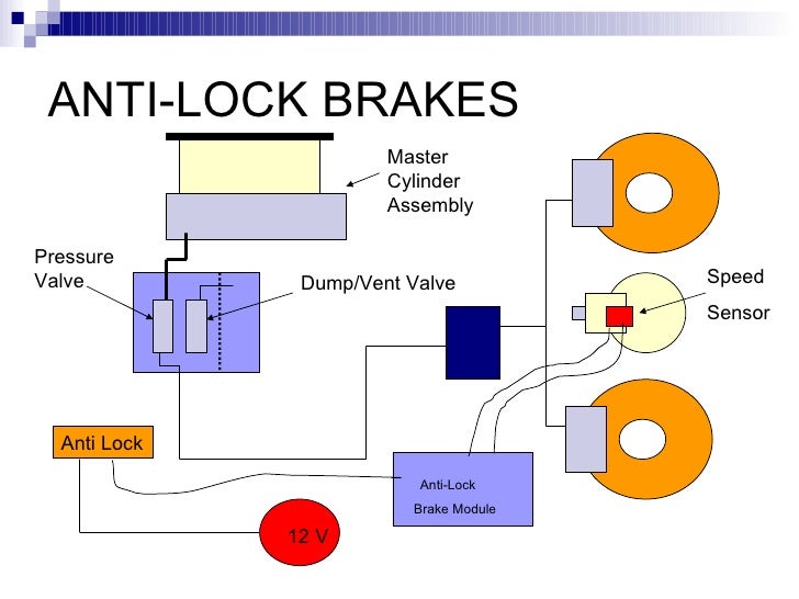
The '73 Eldorado's ABS, often referred to as "Trackmaster," was a rear-wheel-only system. Let's break down the core components:
- Wheel Speed Sensors: Located on the rear wheels, these sensors generated a signal proportional to wheel speed. They were typically variable reluctance sensors, using a toothed wheel (reluctor ring) rotating near a coil of wire. As the teeth passed, they changed the magnetic field, inducing a voltage signal.
- Electronic Control Unit (ECU): The "brain" of the system. The ECU processed the signals from the wheel speed sensors and determined when wheel lockup was imminent. It contained analog circuitry and comparators to analyze the sensor data.
- Hydraulic Modulator: This was the heart of the system, responsible for controlling brake pressure to the rear wheels. It typically consisted of a solenoid-operated valve that could release pressure from the rear brakes when lockup was detected.
- Brake Booster and Master Cylinder: The standard hydraulic system components that provided the initial braking force. The ABS modulator worked in conjunction with these components, not replacing them.
- Warning Light: Located on the dashboard, the ABS warning light indicated a system malfunction.
- Relay: A electrically operated switch, activated by the ECU to control the hydraulic modulator.
Diagram Symbols: Decoding the Language
Understanding the symbols in the diagram is essential for interpreting its information. Here's a breakdown of common elements:
- Lines:
- Solid Lines: Typically represent wires carrying electrical current. The thickness might indicate wire gauge.
- Dashed Lines: Often used to represent hydraulic lines carrying brake fluid.
- Dotted Lines: Can indicate a mechanical connection or a signal path within a component.
- Colors: Wire colors are crucial for tracing circuits. The diagram will likely have a color key, such as:
- Red: Usually indicates power supply.
- Black: Typically ground.
- Other colors: Used for various signal and control wires.
- Icons: Standard electrical symbols are used for components. Here are a few examples:
- Resistor: A zig-zag line.
- Capacitor: Two parallel lines.
- Diode: A triangle pointing to a vertical line.
- Ground: Three horizontal lines decreasing in size.
- Relay Coil: A coiled line with terminals.
- Solenoid: A coil wrapped around a core, often with an arrow indicating movement.
How It Works: A Simplified Explanation
The 1973 Eldorado ABS worked by preventing rear wheel lockup during braking. Here's the process:
- The wheel speed sensors continuously monitor the rotation speed of the rear wheels.
- The ECU receives these signals and compares the wheel speeds.
- If one or both rear wheels decelerate rapidly, indicating impending lockup (e.g., during hard braking on a slippery surface), the ECU activates the hydraulic modulator.
- The hydraulic modulator releases pressure from the rear brakes, allowing the wheels to regain traction.
- Once the wheel speed increases, the ECU releases the pressure release and allows pressure to be applied, therefore reapplying the brakes.
- The ECU cycles this process (pressure release and apply) rapidly – several times per second – to maintain optimal braking force without locking the wheels. This allows the driver to maintain steering control during braking.
Important Note: This early ABS system was relatively unsophisticated. It primarily focused on preventing rear-wheel lockup and didn't have the advanced features of modern ABS, such as individual wheel control or electronic brake-force distribution (EBD).
Real-World Use: Basic Troubleshooting Tips
If your '73 Eldorado's ABS isn't working correctly, here are some basic troubleshooting steps (always consult a qualified mechanic if you're unsure):
- Check the ABS warning light: Is it on? Does it come on briefly when you start the car and then go out? If it stays on, there's a problem.
- Inspect the wheel speed sensors: Check for damage to the sensors, wiring, and reluctor rings. Clean any debris from the sensors. Use a multimeter to test the sensor output (refer to the service manual for specifications).
- Examine the hydraulic modulator: Look for leaks or corrosion. Check the electrical connections.
- Check the wiring: Look for loose connections, damaged wires, or corrosion. Use the diagram to trace circuits and identify potential faults.
- Test the relay: use a multimeter to check the relay, make sure the relay is receiving power.
- Check fuses: ABS systems have dedicated fuses. Use the diagram to identify the location of the fuses.
Safety First: Handle with Care
Working on any braking system requires extreme caution. Here are some critical safety considerations:
- Brake Fluid: Brake fluid is corrosive and can damage paint. Wipe up spills immediately.
- Hydraulic Pressure: The braking system operates under high pressure. Depressurize the system before disconnecting any hydraulic lines.
- Electrical Components: Disconnect the battery before working on electrical components to prevent shocks or damage to the ECU.
- Professional Help: If you're not comfortable working on the braking system, consult a qualified mechanic. Incorrect repairs can have serious consequences.
- Testing: After any repairs, thoroughly test the braking system in a safe environment. Ensure the ABS is functioning correctly before driving on public roads.
Important: The hydraulic modulator contains pressurized brake fluid and sensitive components. Mishandling can result in injury or damage. If you suspect a problem with the modulator itself, it's best left to a professional.
Understanding the 1973 Eldorado ABS diagram is a valuable skill for any classic car enthusiast. It provides insight into the system's operation, aids in troubleshooting, and is essential for restoration and maintenance. Remember to prioritize safety and consult a qualified mechanic if you're unsure about any aspect of the repair process.
We have a high-resolution scan of the 1973 Eldorado ABS diagram ready for you. It's a comprehensive resource that will be invaluable for your restoration or repair project.