1979 Ford F150 Ignition Switch Wiring Diagram
Okay, let's dive into the ignition switch wiring diagram for the 1979 Ford F150. Understanding this diagram is crucial whether you're tackling a no-start issue, rewiring your truck, or simply deepening your knowledge of classic automotive systems. This isn't just some abstract schematic; it's a roadmap to your truck's electrical heart, and knowing how to read it can save you time, money, and a whole lot of frustration. We'll break it down in a way that's both technically accurate and easy to follow.
Purpose of Understanding the Diagram
Why bother learning about this diagram in the first place? Well, there are several key reasons:
- Troubleshooting No-Start Conditions: The ignition switch is often a primary suspect when your truck refuses to crank. The diagram helps you trace the power flow and identify faulty components.
- Electrical Repairs: Damaged wiring around the ignition switch is common in older vehicles. The diagram allows you to correctly repair or replace wires, ensuring proper connections.
- Aftermarket Modifications: Adding accessories like remote starters or alarm systems requires understanding the ignition switch wiring to tap into the correct circuits.
- Restoration Projects: If you're restoring a '79 F150, this diagram is invaluable for verifying the original wiring and correcting any previous modifications.
- Educational Purposes: Even if you don't have an immediate need, understanding the ignition system is a valuable skill for any automotive enthusiast.
Key Specs and Main Parts
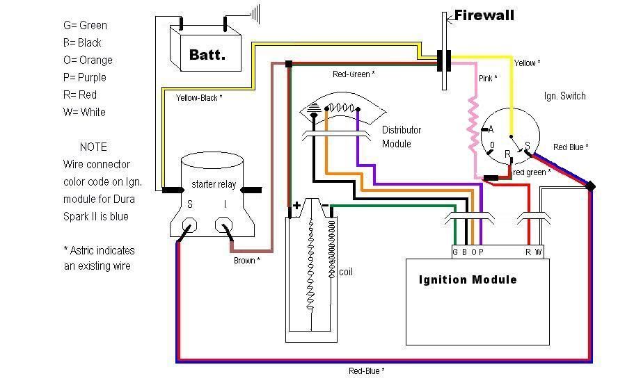
Before we jump into the diagram itself, let's identify the core components and their functions:
- Ignition Switch: This is the central control point. It's a multi-position switch that controls various electrical circuits based on the key position (OFF, ACC, RUN, START).
- Battery: The source of electrical power for the entire system. Typically a 12-volt battery.
- Starter Solenoid: A high-current relay that engages the starter motor when the ignition switch is in the START position. In this era of Fords, the solenoid is usually mounted on the inner fender.
- Starter Motor: The electric motor that cranks the engine to initiate combustion.
- Ignition Coil: Provides the high voltage necessary to create a spark at the spark plugs.
- Ballast Resistor (or Resistance Wire): Used to reduce voltage to the ignition coil during the RUN position, extending coil life. This is an important component to diagnose if it is failing.
- Fuse Box: Contains fuses and circuit breakers to protect electrical circuits from overcurrents.
- Wiring Harness: A collection of wires bundled together, connecting various components.
Understanding the Symbols
Wiring diagrams use a standardized set of symbols to represent components and connections. Here's a breakdown of common symbols you'll encounter:
- Lines: Represent wires. Thicker lines may indicate wires carrying higher current.
- Dots: Indicate a wire connection or splice. Where lines cross without a dot, they are *not* connected.
- Ground Symbol: Usually looks like a downward-pointing triangle or stacked horizontal lines. Indicates a connection to the vehicle's chassis, providing a return path for the current.
- Battery Symbol: Represented by alternating long and short parallel lines, indicating positive (+) and negative (-) terminals.
- Switch Symbol: A line that either connects or disconnects two points, depending on the switch position.
- Resistor Symbol: A zigzag line, representing a component that restricts current flow.
- Fuse Symbol: A wavy line, usually enclosed in a rectangle, representing a fuse that protects a circuit.
Color Codes: The wiring in your '79 F150 is color-coded to help identify circuits. While the exact colors may vary slightly depending on the specific model and year, some common colors include:
- Red: Typically used for circuits connected directly to the battery (always hot).
- Black: Typically used for ground connections.
- Yellow: Often used for circuits powered when the ignition is in the RUN position.
- Brown: Can be used for circuits related to lights.
- White: Can be used for various circuits.
Note: Always double-check the wiring diagram for your specific vehicle to confirm the color codes, as they can vary.
How It Works: The Ignition Sequence
Let's trace the flow of electricity through the ignition system when starting your '79 F150:
- OFF Position: No circuits are energized. The key is removed, and the truck is completely shut down.
- ACC (Accessory) Position: Some circuits are energized, allowing you to use accessories like the radio without starting the engine. Power flows from the battery through the ignition switch to these accessory circuits.
- RUN Position: Most circuits are energized, including the ignition coil, fuel pump (if equipped with an electric pump), and other engine management systems. Power flows from the battery through the ignition switch to these circuits. The ballast resistor reduces the voltage supplied to the coil to extend coil life.
- START Position: The starter solenoid is energized, which then engages the starter motor to crank the engine. In this position, the circuit powering the ignition coil may bypass the ballast resistor to provide a stronger spark for starting (depending on the specific wiring). Once the engine starts, you release the key, and it returns to the RUN position.
Real-World Use: Basic Troubleshooting
Here's how you can use the wiring diagram to troubleshoot common ignition problems:
- No Crank, No Start: Use a multimeter to check for voltage at the starter solenoid when the key is in the START position. If there's no voltage, trace the wiring back to the ignition switch. A faulty ignition switch or a broken wire in the START circuit could be the culprit.
- Engine Cranks But Doesn't Start: Check for spark at the spark plugs. If there's no spark, investigate the ignition coil, ballast resistor (if equipped), distributor (points or electronic ignition module), and related wiring. The diagram will help you identify the correct wires to test.
- Accessories Not Working in ACC Position: Check the fuse for the accessory circuit. If the fuse is good, use the diagram to trace the wiring from the ignition switch to the accessory circuit.
Important: Always use a multimeter to test for voltage and continuity, and be sure to disconnect the battery's negative terminal before working on electrical components.
Safety Considerations
Working with automotive electrical systems can be dangerous. Here are some key safety precautions:
- Disconnect the Battery: Always disconnect the negative (-) battery cable before working on any electrical components to prevent shorts and accidental activation of circuits.
- Be Aware of "Hot" Wires: Some wires are always powered, even with the ignition off. The diagram will help you identify these "hot" wires.
- Use Proper Tools: Use insulated tools and a multimeter designed for automotive use.
- Don't Modify Wiring Without a Plan: Changing wiring without understanding the consequences can lead to electrical fires or damage to your vehicle.
- Be Careful With the Ignition Coil: The ignition coil generates high voltage and can deliver a painful (and potentially dangerous) shock. Avoid touching the coil's output terminals while the engine is running or the ignition is on.
Components of Risk: Especially in older vehicles, be aware of the possibility of corroded wires or damaged insulation. This can cause short circuits or intermittent problems.
Conclusion
Understanding the 1979 Ford F150 ignition switch wiring diagram is a valuable skill for any DIY mechanic or automotive enthusiast. By understanding the components, symbols, and flow of electricity, you can effectively troubleshoot electrical problems, perform repairs, and even modify your truck's electrical system with confidence. Remember to always prioritize safety and use proper tools and techniques.
We have the wiring diagram file, and you can download it to assist you with your projects.