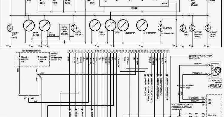
1985 Chevy Truck Wiring Diagram Free
Alright, let's dive into the fascinating world of 1985 Chevy Truck wiring diagrams. These diagrams are your *absolute best friend* when it comes to tackling electrical issues, modifications, or even just understanding how your classic square body is wired. Forget fumbling around in the dark – a good wiring diagram illuminates the path to successful automotive electrical work. We're talking about troubleshooting everything from a flickering headlight to a completely dead ignition system. Understanding and using this resource accurately is a game changer.
Purpose of the 1985 Chevy Truck Wiring Diagram
Why bother with a wiring diagram? Simple: it's the roadmap to your truck's nervous system. It serves several critical purposes:
- Troubleshooting Electrical Problems: Pinpointing the source of electrical faults, from shorts to open circuits, becomes significantly easier with a diagram. You can trace the path of electricity and identify the component causing the issue.
- Performing Repairs: Whether you're replacing a faulty sensor or repairing damaged wiring, the diagram shows you exactly how everything is connected.
- Installing Aftermarket Accessories: Adding things like aftermarket stereos, lights, or even performance upgrades requires knowing where to tap into the existing electrical system. A wiring diagram prevents you from creating a short circuit or damaging your truck's electronics.
- Understanding Your Truck's Electrical System: Even if you're not currently experiencing problems, studying the diagram helps you understand the flow of electricity within your vehicle. This knowledge is invaluable for future repairs and modifications.
- Restoration Projects: For those restoring a classic Chevy truck, the wiring diagram is essential for ensuring the electrical system is wired correctly and safely.
Key Specs and Main Parts
The 1985 Chevy Truck wiring system is a 12-volt DC system. That's a crucial detail. It's also worth noting that the wiring system evolved over the production run, so if you find discrepancies between your diagram and your truck, double check your truck's production date against diagram revisions.
Here are some key components you'll find represented on the diagram:
- Battery: The source of power for the entire electrical system. Usually denoted with the symbol of parallel lines of differing length and indicated polarity.
- Alternator: Charges the battery and provides power when the engine is running. Often represented as a circle with "ALT" inside.
- Starter: Cranks the engine. A circular symbol with "STR" often inside.
- Fuse Box (or Fuse Panel): Contains fuses that protect circuits from overcurrent. Typically shown as a rectangle housing individual fuse symbols.
- Relays: Electrically operated switches that control high-current circuits. Represented as a square with internal circuitry.
- Switches: Control various electrical components, such as headlights, wipers, and ignition.
- Lights: Headlights, taillights, brake lights, etc. Usually shown as a circle with an "X" inside or a bulb symbol.
- Sensors: Devices that monitor various engine parameters (temperature, pressure, etc.) and send signals to the computer.
- Actuators: Devices that control mechanical components based on signals from the computer (fuel injectors, EGR valve, etc.).
- Grounds: Points where electrical circuits are connected to the vehicle's chassis, providing a return path for current. Ground connections are *vital* for proper electrical function. They are usually denoted by an inverted triangle or a series of parallel lines.
Understanding the Symbols
Wiring diagrams use standardized symbols to represent electrical components and connections. Understanding these symbols is essential for interpreting the diagram correctly.
- Lines: Lines represent wires. The thickness of the line might, in some diagrams, represent wire gauge (thicker lines for heavier gauge wires).
- Colors: Wires are color-coded to help identify them. The diagram will have a key explaining the color codes (e.g., "BLU" for Blue, "GRN" for Green, "BLK" for Black, "RED" for Red, "WHT" for White, "YEL" for Yellow). Pay close attention to these color codes, as using the wrong wire can cause serious damage.
- Junctions: Points where wires connect are usually shown as dots or small circles. A staggered "T" intersection means a crossing wire and no electrical connection. A "T" intersection with a dot at the intersection signifies wires connected.
- Component Symbols: As mentioned above, each component (fuse, relay, switch, etc.) has a specific symbol.
- Numbers and Letters: These are often used to identify circuits and connector pin numbers. These are critical for tracing circuits and making sure you are probing the correct wire.
- Splices: These show where one wire branches into multiple wires.
Important Note: Different manufacturers and even different editions of diagrams may use slightly different symbols. However, most of the core symbols are standardized.
How It Works: Tracing a Circuit
The key to using a wiring diagram effectively is to understand how to trace a circuit. Let's say you want to troubleshoot why your headlights aren't working.
- Locate the Headlight Circuit: Find the section of the diagram that shows the headlight circuit. This might be labeled "Headlights" or "Lighting System."
- Identify the Power Source: Start at the power source (the battery or a fuse connected to the battery).
- Follow the Wire: Trace the wire from the power source through the circuit. It will likely pass through a fuse, a switch (the headlight switch), a relay (possibly), and then to the headlights themselves.
- Check for Breaks: As you trace the circuit, look for potential points of failure: blown fuses, corroded connections, damaged wiring, or faulty switches.
- Use a Multimeter: Use a multimeter to check for voltage at various points along the circuit. This will help you pinpoint where the power is being interrupted. If you have voltage at the fuse but not at the headlight, the problem lies somewhere in between.
By systematically tracing the circuit, you can isolate the problem and determine the necessary repair.
Real-World Use: Basic Troubleshooting Tips
Here are some practical tips for using the wiring diagram in real-world troubleshooting scenarios:
- Start with the Basics: Before diving into the diagram, check the obvious things: fuses, bulbs, and connections.
- Use a Multimeter: A multimeter is your best friend for electrical troubleshooting. Learn how to use it to check for voltage, continuity, and resistance.
- Test Lights First: A simple test light can quickly tell you if power is reaching a component.
- Check Ground Connections: Poor ground connections are a common cause of electrical problems. Clean and tighten any ground connections you find. Use a wire brush or sandpaper to remove corrosion.
- Look for Damaged Wiring: Inspect wires for cuts, abrasions, or corrosion. Pay particular attention to areas where wires pass through metal panels or are exposed to the elements.
- Consult Technical Service Bulletins (TSBs): Search online for TSBs related to your specific truck model and year. These bulletins often contain information about common electrical problems and their solutions.
Safety First!
Working with automotive electrical systems can be dangerous if proper precautions are not taken. Here are some important safety guidelines:
- Disconnect the Battery: Always disconnect the negative battery cable before working on any electrical component. This prevents accidental shorts and shocks. This is non-negotiable.
- Use Insulated Tools: Use tools with insulated handles to avoid electric shock.
- Avoid Water: Never work on electrical systems in wet conditions.
- Be Careful with Airbags: Airbag systems contain high-voltage capacitors that can deliver a dangerous shock. If you're working near airbags, follow the manufacturer's instructions for disabling the system.
- High-Current Circuits: Be extremely careful when working with high-current circuits, such as the starter and alternator circuits. These circuits can generate a lot of heat and sparks if shorted.
- Consult a Professional: If you're not comfortable working on electrical systems, consult a qualified mechanic. It's better to be safe than sorry.
Particularly important is the airbag system. Modern airbag systems have capacitors that can store a significant electrical charge long after the battery is disconnected. Accidentally triggering an airbag can cause serious injury. If you are unsure about working around airbags, leave it to a professional. Similarly, the starting system uses very high current. A short in this system can quickly lead to a fire.
We have the 1985 Chevy Truck Wiring Diagram file available for download. It is a valuable resource that will aid you in your electrical work on your truck.