1985 Ford F150 Starter Solenoid Wiring Diagram
The 1985 Ford F150. A workhorse. Simple, reliable, and, let's face it, getting on in years. One area where age can start to show its face is the electrical system. And one component that's frequently a culprit in starting issues is the starter solenoid. Understanding its wiring is crucial for diagnosing problems, performing repairs, and even undertaking modifications. That's where having a solid grasp of the starter solenoid wiring diagram comes in handy.
Why You Need This Diagram
This isn't just about replacing a faulty solenoid. Knowing the wiring allows you to:
- Diagnose Starting Problems: Is it the solenoid, the starter itself, the ignition switch, or a wiring fault? The diagram helps you trace the circuit and pinpoint the problem.
- Perform Repairs Correctly: Avoid costly mistakes and potential electrical fires by ensuring you're connecting wires properly.
- Undertake Modifications: Upgrading your starter or installing a remote start system? The diagram is essential for understanding how to integrate new components.
- General Learning: Expanding your automotive knowledge helps you become a more confident and capable DIY mechanic.
Key Specs and Main Parts of the 1985 F150 Starter System
Before diving into the diagram, let's define the key components:
- Battery: The source of electrical power for the entire system. Typically a 12V lead-acid battery.
- Ignition Switch: Activates the starting circuit when you turn the key to the "start" position.
- Starter Solenoid (Also Known as a Starter Relay): A heavy-duty electromagnetic switch that connects the battery directly to the starter motor. This is mounted separately from the starter on these older fords. It usually resides on the inner fender, near the battery.
- Starter Motor: An electric motor that spins the engine's flywheel, initiating the combustion process.
- Neutral Safety Switch (Automatic Transmissions Only): Prevents the engine from starting unless the transmission is in Park or Neutral. This is crucial for safety.
- Wiring Harness: The network of wires that connects all the components.
Decoding the Wiring Diagram: Symbols and Colors
A wiring diagram is a symbolic representation of the electrical circuit. Understanding these symbols is key to reading the diagram correctly.
- Lines: Represent wires. Thicker lines often indicate wires carrying higher current. Dashed lines may indicate a wire hidden or internal to a component.
- Colors: Each wire is color-coded. These colors are usually abbreviated (e.g., "Red" might be "R" or "RD," "Black" might be "BK"). Consult a color code chart specific to Ford for accurate identification. Common colors include Red, Black, Yellow, Blue, and Green. Consistent color coding between diagram and real life is essential for avoiding miswiring.
- Circles/Dots: Indicate a connection point between wires. A dot where lines intersect means the wires are electrically connected. If lines cross without a dot, they are *not* connected.
- Rectangles/Squares: Represent components like switches, relays, or the starter solenoid itself.
- Ground Symbol: Usually a series of horizontal lines or a triangle, indicating a connection to the vehicle's chassis, which serves as the return path for the electrical current.
- Component Symbols: The diagram will use standardized symbols for the ignition switch, starter motor, neutral safety switch, etc. These symbols should be labeled with the component name.
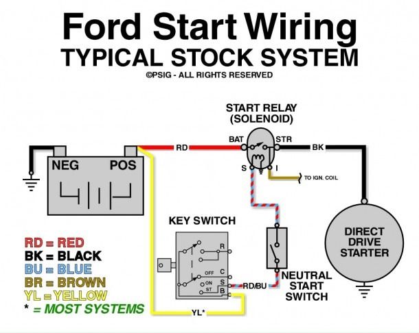
A typical 1985 Ford F150 starter solenoid wiring diagram will show the following key connections:
- Battery Positive (+) to One Large Solenoid Terminal: This is the direct feed from the battery.
- Other Large Solenoid Terminal to Starter Motor Positive (+): This wire carries the high current to power the starter.
- Small "S" Terminal on Solenoid to Ignition Switch (Start Position): When the ignition switch is turned to "start," it sends a signal to this terminal, energizing the solenoid's electromagnet. Often routed through the Neutral Safety Switch.
- Small "I" Terminal on Solenoid (Sometimes Present): This terminal *may* be present and provides a full 12V to the ignition system during cranking, bypassing the ballast resistor (if equipped) for a hotter spark during startup. Not all 1985 F150s used this configuration.
- Solenoid Case/Mounting to Ground: The solenoid needs a good ground connection to function correctly.
How It Works: The Starting Sequence
Here’s a breakdown of the electrical flow when you turn the key:
- Turning the ignition key to the "start" position sends a small current through the wire connected to the "S" terminal of the starter solenoid. This current may first pass through a neutral safety switch, if equipped on an automatic transmission.
- This small current energizes an electromagnet inside the solenoid.
- The energized electromagnet pulls a metal contactor inside the solenoid, bridging the two large terminals.
- Bridging the terminals completes the circuit between the battery and the starter motor.
- The starter motor engages and spins the engine's flywheel, initiating the combustion process.
- When the engine starts and you release the key, the ignition switch cuts power to the solenoid, the electromagnet de-energizes, and the contactor separates, disconnecting the starter motor from the battery.
Real-World Use: Basic Troubleshooting
Here are a few common issues and how the wiring diagram can help:
- Engine Cranks Slowly or Not at All: Check the battery voltage. Then, use a multimeter to check for voltage at the large terminals of the solenoid when the key is in the "start" position. If voltage is present *but* the starter isn't engaging, the starter motor itself may be faulty. If no voltage is present at the large terminals *after* the "S" terminal is powered, the solenoid is likely bad.
- Clicking Sound, But No Cranking: This often indicates a weak battery, a corroded connection, or a faulty solenoid. Clean the battery terminals and check the ground connections to the solenoid and starter motor. If the connections are good, the solenoid is likely the culprit. You can also use a jumper cable to carefully bypass the solenoid (connecting the two large terminals). If the starter engages, it confirms the solenoid is the problem. Use extreme caution when bypassing the solenoid.
- Engine Cranks Continuously: This could indicate a stuck solenoid contactor or a faulty ignition switch. Replace the solenoid. If it persists, inspect the ignition switch.
- No Response When Turning the Key: Check the ignition switch, the neutral safety switch (if applicable), and the wiring to the "S" terminal of the solenoid. A test light or multimeter can help you trace the circuit and identify any breaks or shorts.
Safety First! Handling Risky Components
Working with the electrical system involves inherent risks. Always disconnect the negative battery cable before working on any electrical components. The starter circuit carries high current, so be extremely careful when working near the solenoid and starter motor. Accidental shorts can cause sparks, burns, and even fires. The battery contains sulfuric acid, which can cause severe burns. Wear appropriate safety gear, including eye protection and gloves.
Bypassing the starter solenoid, as mentioned in the troubleshooting section, should only be done briefly for diagnostic purposes and with extreme caution. A misplaced tool or accidental short can have severe consequences.
Remember to double-check all connections after completing any work. A loose connection can cause intermittent problems and potentially damage other components.
You can use the diagnostic steps with wiring diagram to test the circuit. Please remember that electricity can be dangerous. Always use caution when working on the electrical system of your vehicle. Never work on the system while the vehicle is running, or if the vehicle is turned on. Disconnect the negative battery cable before you start.
We have the 1985 Ford F150 Starter Solenoid Wiring Diagram available for download. It's a valuable resource to keep on hand for repairs and modifications.