1986 Ford F150 Starter Solenoid Wiring Diagram
Let's dive into the 1986 Ford F150 starter solenoid wiring diagram. Understanding this circuit is crucial for anyone maintaining, troubleshooting, or modifying this classic truck. Whether you're dealing with a no-start condition, upgrading your electrical system, or just want to know how things work, this guide will equip you with the knowledge you need.
Purpose of the Starter Solenoid Wiring Diagram
The wiring diagram is essentially a roadmap of the electrical connections for the starter solenoid circuit. Its primary purpose is to:
- Diagnose Electrical Problems: Pinpoint breaks, shorts, or incorrect connections within the starter circuit.
- Perform Repairs: Ensure wires are connected to the correct terminals after replacing components.
- Undertake Modifications: Safely integrate aftermarket components, such as alarms or remote starters.
- General Understanding: Gain a deeper understanding of how your truck's starting system operates.
Without this diagram, you're essentially troubleshooting in the dark, relying on guesswork that can lead to further damage or incorrect repairs. With it, you can systematically trace the circuit and identify the root cause of the problem.
Key Specs and Main Parts
Before we look at the specifics of the diagram, let’s identify the main components involved in the starting system of a 1986 Ford F150.
- Battery: Provides the initial electrical power (typically 12 volts DC).
- Ignition Switch: Activates the starting circuit when turned to the "Start" position.
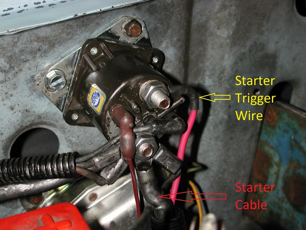
- Starter Solenoid: An electromagnetic switch that uses a small current from the ignition switch to control a much larger current flow to the starter motor. In 1986 F150s, this is usually mounted on the inner fender well, typically near the battery.
- Starter Motor: A powerful electric motor that engages with the flywheel (or flexplate) to crank the engine.
- Wiring Harness: A bundle of wires that connect all these components.
Typical Wiring Specs:
- Heavy Gauge Cables: Used for the battery-to-solenoid and solenoid-to-starter connections due to the high current draw. Typically 4 or 6 gauge.
- Lighter Gauge Wires: Used for the control wires from the ignition switch to the solenoid. Typically 16 or 18 gauge.
- Voltage: Primarily 12 volts DC.
Understanding the Symbols in the Wiring Diagram
Wiring diagrams use a universal language of symbols to represent electrical components and connections. Here's a breakdown of what you'll commonly find:
Lines
- Solid Lines: Represent wires. The thickness may (but doesn’t always) indicate the wire gauge (thicker lines = larger gauge).
- Dashed Lines: Sometimes used to indicate wires or connections that are part of a separate subsystem or that may only be present on certain models.
- Lines Crossing: A simple crossing line generally indicates that wires pass each other without making an electrical connection.
- Lines with a Dot: A dot where lines intersect indicates an electrical connection between the wires.
Colors
Wire colors are crucial for identification. Common colors and their usual functions:
- Red: Typically indicates a positive ( + ) power source from the battery.
- Black: Usually indicates ground ( – ).
- Yellow: Often associated with ignition circuits.
- Purple: Can be used for circuits controlled by the ignition switch.
- Green: Frequently used for sensor grounds or other grounding points.
Important Note: Wire color codes can vary slightly depending on the specific year and trim level of your F150. Always double-check with the diagram specific to your vehicle.
Icons
- Battery Symbol: Represents the battery (positive and negative terminals).
- Solenoid Symbol: A coil symbol with terminals marked "S" (start) and "I" (ignition) or similar.
- Starter Motor Symbol: Often a circle with an "M" inside or a stylized representation of the starter motor.
- Ground Symbol: Indicates a connection to the vehicle's chassis, providing a return path for the current.
- Fuse Symbol: A zigzag line inside a rectangle, indicating a fuse for circuit protection.
- Switch Symbol: Indicates the ignition switch with different positions (Off, Run, Start).
How the Starter Solenoid Circuit Works
The starting circuit works as follows:
- When you turn the ignition key to the "Start" position, a small current flows from the battery, through the ignition switch, and to the "S" terminal of the starter solenoid.
- This small current energizes the solenoid's internal electromagnet.
- The electromagnet pulls a contactor (a heavy-duty switch) inside the solenoid closed.
- This closes the circuit between the battery positive terminal and the starter motor. A *very large* current now flows directly from the battery to the starter motor.
- The starter motor engages with the flywheel and cranks the engine.
- When you release the key, the current to the solenoid is cut off, the electromagnet de-energizes, and the contactor opens, stopping the flow of current to the starter motor.
Real-World Use: Troubleshooting the Starter Circuit
Here are some common problems and how to troubleshoot them using the wiring diagram:
- No Start, No Click: If you turn the key and nothing happens, not even a click from the solenoid, check the following:
- Battery voltage.
- The connection from the battery to the solenoid.
- The ignition switch. Use a multimeter to check for voltage at the "S" terminal of the solenoid when the key is in the "Start" position. If no voltage, the problem is upstream, in the ignition switch or wiring between the switch and solenoid.
- Ground connection: Ensure the starter solenoid is properly grounded to the chassis.
- No Start, Click Only: If you hear a clicking sound from the solenoid but the engine doesn't crank, this usually indicates:
- A weak battery.
- A poor connection between the solenoid and the starter motor. Check the heavy-gauge cable and terminals for corrosion.
- A faulty starter motor.
- Starter Motor Cranks Slowly:
- A weak battery.
- Poor connections in the starter circuit (corrosion, loose terminals).
- A failing starter motor.
Always use a multimeter to check for voltage and continuity when troubleshooting electrical circuits.
Safety Precautions
Working with electrical systems can be dangerous. Here are some crucial safety tips:
- Disconnect the Battery: Always disconnect the negative battery cable before working on any electrical components. This prevents accidental shorts and potential shocks.
- Use Insulated Tools: Use tools with insulated handles to avoid electrical shocks.
- Work in a Well-Ventilated Area: Batteries can produce hydrogen gas, which is flammable.
- Avoid Working Alone: It's always safer to have someone nearby in case of an emergency.
- Be Careful with High Current: The starter motor circuit carries a very high current. Avoid touching exposed terminals or wires when the circuit is active.
The battery, starter solenoid, and starter motor are the most risky components due to the high current they carry. Handle them with extreme caution.
Remember to double-check your work and consult the wiring diagram throughout the process. With a little patience and attention to detail, you can successfully diagnose and repair your 1986 Ford F150's starter system.
For your convenience, we have the complete 1986 Ford F150 starter solenoid wiring diagram available for download. This will provide you with a detailed visual aid to complement this guide.