1990 Ford F150 Starter Solenoid Wiring Diagram
Alright, let's dive into the 1990 Ford F150 starter solenoid wiring diagram. Whether you're tackling a no-start issue, doing some electrical modifications, or just trying to better understand your truck's starting system, knowing this diagram inside and out is invaluable. We're going to break it down like I would if you were standing next to me in the shop. You don't need to be an electrical engineer to understand this; just a willingness to learn.
Purpose of the Wiring Diagram
This diagram isn't just a pretty picture. It's your roadmap to understanding and troubleshooting the entire starter circuit. Specifically, the diagram helps you:
- Diagnose starting problems: No-start, slow crank, clicking noises – the diagram helps you trace the fault.
- Perform repairs: Replacing a faulty solenoid, wiring harness repair, or component upgrades become much easier.
- Understand the system: Knowing how the components interact allows you to anticipate potential issues and prevent failures.
- Modify the system: Adding aftermarket accessories like remote starters requires a solid understanding of the existing wiring.
Think of it as a translator. The engine speaks through electrical signals, and the wiring diagram helps you decipher those signals.
Key Specs and Main Parts
The 1990 F150 starter circuit, while relatively simple, relies on a few critical components:
- Battery: Provides the initial power to the entire system. Usually a 12-volt lead-acid battery.
- Ignition Switch: When you turn the key, it sends a signal to the starter solenoid.
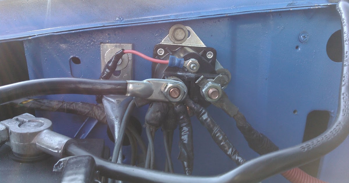
- Starter Solenoid (Also called Starter Relay): This is the heart of the system. It's a high-current switch that connects the battery directly to the starter motor. On the 1990 F150, it's typically mounted on the fender well.
- Starter Motor: The device that physically cranks the engine.
- Neutral Safety Switch (NSS) or Transmission Range Sensor (TRS): Prevents the engine from starting unless the transmission is in Park or Neutral. A critical safety feature!
- Wiring Harness: The network of wires that connects all these components.
- Fuses and Fusible Links: Protection devices that prevent damage from overcurrent.
Voltage is the electrical potential, the 'push' behind the current. Current (measured in Amps) is the flow of electrical charge. Resistance (measured in Ohms) opposes the flow of current. These three are related by Ohm's Law: Voltage = Current x Resistance (V = IR). Understanding these basics is essential for troubleshooting electrical issues.
Symbols: Deciphering the Diagram
Wiring diagrams use standardized symbols to represent components and connections. Here’s a breakdown of common symbols you'll encounter:
- Solid Lines: Represent wires. The thickness of the line doesn't necessarily indicate wire gauge, but typically heavier lines represent higher current carrying capacity.
- Dashed Lines: Often indicate shielded wires or circuits that are optional or only present on certain models.
- Circles: Represent connections or splices.
- Rectangles: Often represent components like relays, switches, or electronic modules.
- Ground Symbol (usually three descending horizontal lines): Indicates a connection to the vehicle's chassis, which serves as the ground return path for the electrical circuit.
Color Codes: The color of the wires is usually indicated on the diagram. Common colors include:
- Red: Typically used for battery positive (+) connections.
- Black: Almost always used for ground (-) connections.
- Other colors (Blue, Green, Yellow, White, etc.): Used for various signal wires and other circuits.
The wiring diagram will often use abbreviations for colors (e.g., RD for Red, BK for Black, BL for Blue, GN for Green, WH for White, YL for Yellow).
How It Works: A Step-by-Step Explanation
Let's trace the flow of electricity from the battery to the starter:
- Battery Power: The battery provides 12 volts to the system. A heavy-gauge cable runs from the positive (+) battery terminal to one of the large terminals on the starter solenoid.
- Ignition Switch Signal: When you turn the ignition key to the "Start" position, it sends a signal (typically a smaller gauge wire, often red/light blue) to the control terminal of the starter solenoid.
- Solenoid Activation: This small current energizes the solenoid's internal electromagnet. This electromagnet pulls a contactor inside the solenoid.
- High-Current Connection: The contactor inside the solenoid bridges the gap between the two large terminals. This allows a high-current path to flow directly from the battery (through the solenoid) to the starter motor.
- Starter Motor Engagement: The high current flows through the starter motor, causing it to spin and engage the engine's flywheel via the starter drive (Bendix). The engine cranks.
- Neutral Safety Switch/TRS: Crucially, the signal from the ignition switch *must* pass through the Neutral Safety Switch or Transmission Range Sensor. If the transmission isn't in Park or Neutral, this switch prevents the signal from reaching the starter solenoid, preventing accidental starting.
When you release the key from the "Start" position, the signal to the solenoid is cut, the electromagnet de-energizes, the contactor opens, and the starter motor stops.
Real-World Use: Basic Troubleshooting
Okay, your truck isn't starting. Here are some common issues and how the wiring diagram can help:
- No Crank, No Click: Check the battery voltage first! Then, use a multimeter to check for voltage at the control terminal of the starter solenoid when the key is in the "Start" position. If no voltage, trace the wiring back to the ignition switch and the Neutral Safety Switch/TRS. A blown fuse or a faulty switch could be the culprit.
- No Crank, Click Sound: This often indicates a weak battery, corroded connections, or a failing starter solenoid. Clean and tighten all connections (battery terminals, solenoid terminals, starter motor terminals). If the connections are good, the solenoid might be failing – its internal contacts are likely burned. Replacing the solenoid is usually the solution.
- Slow Crank: Indicates a weak battery, excessive resistance in the starter circuit, or a worn starter motor. Again, check the battery and connections. A voltage drop test can help pinpoint areas of high resistance.
- Starter Stays Engaged: Usually a faulty starter solenoid that's stuck in the "on" position. Replace the solenoid immediately!
Remember to use a multimeter to check for voltage and continuity when troubleshooting. Continuity is a complete electrical path – the opposite of an open circuit. Always disconnect the battery's negative terminal before working on the electrical system to prevent short circuits and potential damage.
Safety: Highlighting Risky Components
The starter circuit deals with high currents. Mishandling these components can lead to serious burns or even electrical fires.
- Battery: Contains corrosive acid. Wear safety glasses and gloves when handling it. Avoid shorting the battery terminals.
- Starter Solenoid: High-current device. Disconnect the battery before working on it.
- Starter Motor: Can get very hot during operation. Avoid touching it immediately after cranking the engine.
Never bypass the Neutral Safety Switch/TRS. This is a critical safety feature designed to prevent accidental starting. Tampering with it is extremely dangerous.
When working on the electrical system, always disconnect the negative battery cable. This eliminates the possibility of accidentally creating a short circuit and damaging components or injuring yourself. And, if you're not comfortable working with electricity, it's always best to consult a qualified mechanic.
Now you have a much better understanding of your truck's starting circuit! Remember, take your time, be methodical, and prioritize safety. With the wiring diagram in hand and a bit of patience, you can tackle many starting system issues yourself.
Good luck with your project!
We have the complete 1990 Ford F150 starter solenoid wiring diagram available for download. This comprehensive resource will provide even more detail and visual clarity to assist you in your troubleshooting and repair efforts. Simply click the link below to access the file.