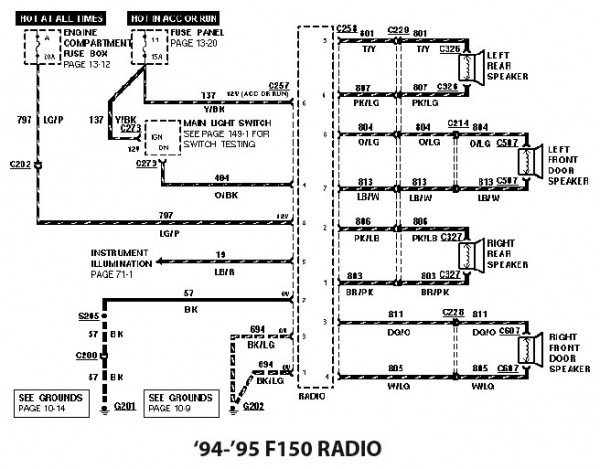
1994 Ford F150 Stereo Wiring Diagram
Let's dive into the stereo wiring diagram for a 1994 Ford F150. This document is crucial for anyone tackling audio upgrades, diagnosing speaker problems, or even just trying to understand the electrical system in your truck better. Knowing your way around this diagram can save you a ton of time and frustration – not to mention prevent costly mistakes. We'll break down the key components, symbols, and functionality to help you navigate it with confidence.
Purpose of the Wiring Diagram
Why bother with a wiring diagram in the first place? Well, think of it as a roadmap for the electrical circuits in your truck's audio system. It provides a visual representation of how all the components – the radio head unit, speakers, antenna, and related wiring – are connected. This is invaluable for:
- Repairs: Identifying broken or frayed wires causing audio issues.
- Upgrades: Safely installing aftermarket radios, amplifiers, or speakers.
- Troubleshooting: Pinpointing the source of problems like no sound, distorted audio, or blown fuses.
- Learning: Understanding the basic electrical principles of your truck's audio system.
Without a diagram, you're essentially guessing, which can lead to damaging components or creating shorts. Trust me; you want to avoid that!
Key Specs and Main Parts
The 1994 Ford F150's audio system is relatively straightforward compared to modern vehicles. The key components you'll find on the wiring diagram are:
- Head Unit (Radio): This is the central control unit, providing the radio, tape (if equipped), and in some cases, CD player functionality. It outputs the audio signal to the speakers.
- Speakers: Typically, the F150 has two speakers in the doors or lower dashboard area. Some models may have rear speakers as well.
- Antenna: Receives the radio signal.
- Wiring Harness: A bundle of wires connecting all the components. This is where a lot of the action (and potential problems) happens.
- Fuses: These are critical safety devices that protect the electrical system from overloads.
- Ground Points: Places where the electrical circuit connects to the vehicle's chassis, providing a return path for the current.
The wiring diagram will show the pinout of the radio, detailing the function of each wire (e.g., power, ground, speaker outputs, illumination). Pay close attention to these details!
Decoding the Symbols
Wiring diagrams use standardized symbols to represent electrical components and connections. Understanding these symbols is essential for interpreting the diagram correctly. Here are some common ones you'll encounter:
- Solid Lines: Represent wires. The thickness may indicate the wire gauge (thicker wires can carry more current).
- Dashed Lines: May represent shielded wires or ground connections.
- Circles: Can represent connectors or junctions where wires meet.
- Resistors: A squiggly line indicating resistance to current flow. These are not common in basic stereo wiring.
- Capacitors: Two parallel lines. These are used for filtering and smoothing signals. Again, less common in basic stereo wiring diagrams for F150s.
- Fuses: A small rectangle with a line through it.
- Ground Symbol: Typically looks like a series of horizontal lines decreasing in size, connected to the circuit.
Color Coding: Perhaps the most crucial aspect of wiring diagrams is the color coding. Each wire is assigned a specific color, and the diagram will indicate these colors. For example, a wire labeled "RD/BK" means it's a red wire with a black stripe. Following the color code ensures you're connecting the right wires to the right terminals. Common colors are Red (power), Black (ground), White (speaker +), and Gray (speaker -), but always double-check!
Icons: The diagram will use icons to represent the radio, speakers, and antenna. These icons are usually simplified drawings of the components.
How It Works: The Electrical Flow
The basic principle is simple: the radio receives power from the truck's battery and ground. It then generates an audio signal, which is amplified (either internally or by an external amplifier) and sent to the speakers. The speakers convert the electrical signal into sound waves that you hear. The antenna receives radio signals and sends them to the radio.
The wiring diagram shows you the path of the electricity from the battery, through the fuse box (to protect the circuit), to the radio, then to the speakers, and back to ground. Understanding this flow helps you troubleshoot problems. For instance, if a speaker isn't working, you can trace the wiring from the radio to the speaker, checking for breaks, loose connections, or shorts along the way.
Real-World Use: Basic Troubleshooting Tips
Let's say your F150's radio suddenly goes silent. Here's how you might use the wiring diagram to troubleshoot:
- Check the Fuse: Locate the fuse for the radio in the fuse box. Use the wiring diagram to identify the correct fuse. If it's blown, replace it with one of the same amperage. If it blows again immediately, there's a short somewhere in the circuit.
- Verify Power and Ground: Using a multimeter, check that the radio is receiving power (usually 12V) and has a good ground connection. The wiring diagram shows you which wires to test. A lack of power or ground is a common cause of radio failure.
- Speaker Connections: If only one speaker isn't working, check the wiring connections at the speaker itself. The wiring diagram will show you the color codes for the speaker wires.
- Head Unit Connections: Check the connections at the back of the radio. Make sure all the wires are securely connected. A loose or corroded connection can cause intermittent problems.
Remember to disconnect the battery's negative terminal before working on any electrical components to prevent shorts and accidental damage.
Safety Considerations
Working with electrical systems can be dangerous if you're not careful. Here are some safety precautions to keep in mind:
- Disconnect the Battery: Always disconnect the negative terminal of the battery before working on the electrical system. This will prevent accidental shorts and electric shock.
- Use Proper Tools: Use insulated tools designed for electrical work.
- Don't Overload Circuits: Never replace a fuse with one of a higher amperage. This can damage the wiring and cause a fire.
- Be Careful with Wiring: Avoid cutting or splicing wires unless you know what you're doing. Use proper wiring connectors and crimping tools to ensure secure connections.
High-Risk Components: Be extra cautious when working with the battery and any wiring connected directly to it. These components carry high current and can cause serious injury if shorted.
Download the Diagram
This article provides a general overview, but having the actual 1994 Ford F150 stereo wiring diagram in front of you is essential. We have the full file available for download. This will give you the specific wire colors, pinouts, and component locations for your truck. With the diagram and a little patience, you'll be able to tackle any audio-related project with confidence. Good luck, and remember to work safely!