
1995 Ford F150 5.0 Vacuum Line Diagram
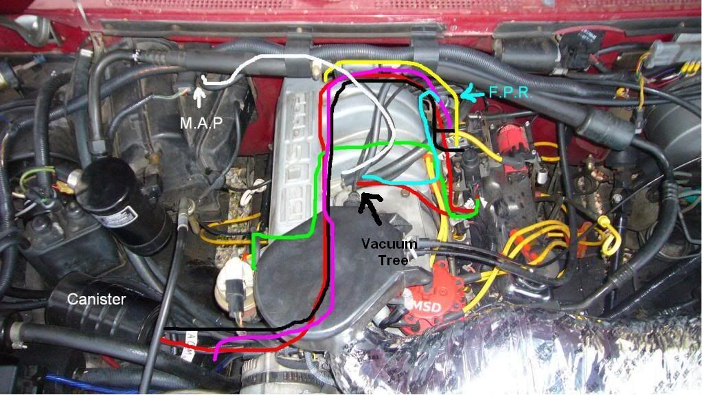
Let's dive into the sometimes-confusing world of vacuum lines on a 1995 Ford F150 with the 5.0L (302 cubic inch) engine. This article provides a detailed explanation of the vacuum line diagram, essential for everything from basic maintenance to more complex engine diagnostics and modifications. We've got the complete diagram file available for download, so you can keep it handy while you work. Understanding your vacuum system can save you time and money, and even help you diagnose problems that might otherwise seem unexplainable.
Why This Diagram Matters
The vacuum system in your '95 F150 is crucial for several functions. It affects everything from engine performance and fuel economy to emissions control and even your HVAC system. A vacuum leak can cause a whole host of problems: rough idling, stalling, poor acceleration, increased fuel consumption, and even issues with your climate control system. The vacuum diagram is your roadmap to understanding this system. It's invaluable for:
- Repairing Vacuum Leaks: Identifying damaged or disconnected hoses is the first step in fixing performance issues.
- Engine Diagnostics: Vacuum readings are a key diagnostic indicator, allowing you to pinpoint engine problems.
- Emissions Compliance: Many vacuum lines are connected to the emissions control system. Proper routing is essential for passing inspections.
- Understanding Engine Operation: Seeing the connections provides insight into how different engine components interact.
- Modifications & Upgrades: Knowing the layout helps when installing aftermarket parts or making performance modifications.
Key Specs and Main Parts
The 1995 Ford F150 5.0L vacuum system isn't overly complex, but it does include several important components interconnected by a network of hoses. Here's a rundown of the key players:
- Intake Manifold: The source of vacuum for the entire system. Engine vacuum is strongest here.
- Vacuum Reservoir (or Canister): A storage tank for vacuum, usually located in the engine bay or fender well. It provides a consistent vacuum supply, especially when engine vacuum fluctuates.
- EGR Valve (Exhaust Gas Recirculation): Controls the recirculation of exhaust gases back into the intake manifold to reduce NOx emissions. It is vacuum-operated.
- TAB/TAD Solenoids (Thermactor Air Bypass/Thermactor Air Diverter): These solenoids control the flow of air from the smog pump (thermactor pump) to the exhaust manifolds. They use vacuum to switch between different air injection modes.
- PCV Valve (Positive Crankcase Ventilation): A crucial component for reducing emissions and maintaining engine health. It vents crankcase gases back into the intake manifold.
- Fuel Pressure Regulator: Regulates fuel pressure to the fuel injectors. It is vacuum referenced, meaning its operation is influenced by intake manifold vacuum.
- MAP Sensor (Manifold Absolute Pressure): Measures manifold pressure and sends data to the PCM (Powertrain Control Module). While it measures pressure, vacuum plays a role in how it functions.
- HVAC System: Vacuum lines control the blend doors and mode doors in your heater and air conditioning system. A vacuum leak here can cause your vents to blow air in the wrong places.
- Vacuum Hoses: The lifelines of the system, connecting all the components.
Understanding the Vacuum Line Diagram: Symbols and Colors
Vacuum diagrams use a standardized set of symbols and (sometimes) colors to represent the different components and hoses. While the exact colors can vary slightly between diagrams, the basic principles remain the same. Here’s a breakdown:
- Lines: Solid lines typically represent vacuum hoses. Dashed lines may represent electrical wiring or internal passages within a component.
- Arrows: Arrows indicate the direction of vacuum flow.
- Circles/Ovals: Represent vacuum reservoirs or other storage devices.
- Squares/Rectangles: Usually represent switches, solenoids, or other control devices.
- T-Connectors/Y-Connectors: Show where one vacuum line splits into two or more.
Color Coding (Common Examples): While not always present, some diagrams use colors to further differentiate hoses based on their function. Refer to the legend on the diagram itself for the specific color codes used on your particular document. Common examples include:
- Black: Often used for the main vacuum supply line from the intake manifold.
- Red: May indicate a vacuum line related to the fuel system.
- Green: Often associated with the EGR system.
- Blue: Can sometimes be used for the HVAC system.
Remember, the legend on your specific diagram is the definitive source for interpreting the symbols and colors used.
How It Works: The Flow of Vacuum
The heart of the vacuum system is the intake manifold. As the engine runs, the pistons move down, creating a partial vacuum in the cylinders. This vacuum is communicated to the intake manifold, which then acts as the primary source of vacuum for the entire system. From the intake manifold, vacuum is distributed to various components through a network of hoses.
The vacuum reservoir acts as a buffer, storing vacuum to ensure a consistent supply even when the engine is under load (when vacuum levels tend to drop). Solenoids, controlled by the PCM, act as switches, routing vacuum to different components based on engine operating conditions. For example, the EGR valve opens to allow exhaust gases into the intake manifold, reducing emissions during certain driving conditions. The TAB/TAD solenoids control the flow of air from the smog pump to the exhaust manifolds, helping to burn off unburned hydrocarbons in the exhaust.
The fuel pressure regulator uses vacuum to adjust fuel pressure based on engine load. When the engine is under high load (low vacuum), the fuel pressure increases to provide more fuel. When the engine is idling (high vacuum), the fuel pressure decreases.
Real-World Use: Basic Troubleshooting Tips
Here are some basic troubleshooting tips using the vacuum line diagram:
- Visual Inspection: Start by visually inspecting all vacuum hoses for cracks, breaks, or disconnections. This is often the most common cause of vacuum leaks. Pay close attention to areas near heat sources or where the hoses are bent sharply.
- Vacuum Gauge: A vacuum gauge is an invaluable tool for diagnosing vacuum leaks. Connect the gauge to a manifold vacuum source (such as a port on the intake manifold) and read the vacuum level at idle. A low or fluctuating vacuum reading can indicate a leak.
- Vacuum Leak Tester: Use a vacuum leak tester (smoke machine) to introduce smoke into the vacuum system and identify the location of leaks. This is particularly useful for finding small or hidden leaks.
- Component Testing: Use a vacuum pump to test individual vacuum-operated components, such as the EGR valve or HVAC actuators. Apply vacuum to the component and observe its operation. If it doesn't function properly, it may be faulty.
- Follow the Diagram: Always refer to the vacuum line diagram to ensure that all hoses are connected correctly. It's easy to accidentally disconnect or misroute a hose during repairs.
Example Scenario: Your '95 F150 is idling roughly. You consult the vacuum diagram and trace the PCV valve hose back to the intake manifold. You find a crack in the hose. Replacing the hose solves the rough idle problem.
Safety Considerations
While working on vacuum lines is generally safe, there are a few things to keep in mind:
- Hot Surfaces: Be careful when working near hot engine components, such as the exhaust manifolds. Allow the engine to cool down before working on vacuum lines in these areas.
- Fuel Lines: Some vacuum lines are located near fuel lines. Be careful not to damage or disconnect fuel lines while working on the vacuum system. Fuel leaks can be a fire hazard.
- Electrical Components: Avoid touching or disconnecting electrical connectors while the engine is running. This can damage the PCM or other electronic components.
- Working with Vacuum Pump: Be cautious when using a vacuum pump to test components. Excessive vacuum can damage some components. Always follow the manufacturer's instructions for the vacuum pump.
A particularly important area to note is the fuel pressure regulator, as it's connected to the fuel rail. Be incredibly careful when working around this component. Relieve fuel pressure before disconnecting any lines in this area. Improper handling of fuel lines can result in a serious fire or explosion.
With the detailed 1995 Ford F150 5.0 vacuum line diagram available for download, you'll be well-equipped to tackle a variety of maintenance, repair, and modification projects. Good luck!
Download the diagram HERE.