
1995 Ford F150 Front Suspension Diagram
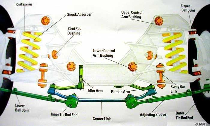
So, you're tackling the front suspension on your '95 Ford F150? Excellent choice. Understanding the system is crucial for successful repairs, modifications, or just plain keeping your truck running smoothly. This article dives deep into the front suspension diagram of your trusty F150, breaking down its components, functionality, and troubleshooting tips. We’ll assume you're already familiar with basic automotive tools and safety practices. Remember, suspension work can be dangerous if not done correctly, so proceed with caution.
Purpose of Understanding the Diagram
Why bother with a diagram? Simple. It's your roadmap. This diagram isn't just a pretty picture; it's a visual representation of how all the suspension components fit together and interact. Using it, you can:
- Diagnose Problems: Pinpoint the source of noises, uneven tire wear, or handling issues.
- Perform Repairs Correctly: Ensure you replace parts in the correct order and with the proper torque specifications.
- Modify with Confidence: Plan upgrades, like lift kits or performance shocks, with a clear understanding of how they'll affect the system.
- Order the Right Parts: Identify the exact components you need, avoiding costly mistakes.
Key Specs and Main Parts
The 1995 Ford F150 utilizes a Twin Traction Beam (TTB) front suspension. This design is known for its robust off-road capability and relatively simple construction. Here are the key components you'll find in the diagram:
- Twin Traction Beams (TTB): These are the heart of the system. They're essentially two independent axles that pivot at the center of the truck. Each beam carries one front wheel. One beam is typically longer than the other.
- Radius Arms: These arms connect the axle beams to the frame. They control axle wrap (twisting under acceleration or braking) and contribute to overall stability.
- Coil Springs: Provide the main source of suspension support, absorbing bumps and maintaining ride height.
- Shock Absorbers (Dampers): Control the oscillation of the springs, preventing excessive bouncing and ensuring a smooth ride.
- Spindles (Knuckles): Connect the wheel hub/bearing assembly to the axle beams. They pivot for steering.
- Ball Joints: Allow for articulation between the spindle and the axle beam. These are critical for steering and suspension movement. Upper and lower ball joints are usually present.
- Tie Rods (Inner and Outer): Part of the steering linkage, connecting the steering gear to the spindles and controlling steering input.
- Stabilizer Bar (Sway Bar): Reduces body roll during cornering, improving handling stability. Connected to the frame and the axle beams via end links.
- Axle Pivot Brackets: These brackets attach the TTB axles to the vehicle frame, providing the crucial pivot points for the independent suspension movement.
- Wheel Hub/Bearing Assembly: Houses the wheel bearings and provides a mounting point for the wheel.
Torque specifications for all these components are critical and can be found in your factory service manual, or in the detailed diagram (which we have available for download). Proper torque ensures components are secure but not over-stressed.
Symbols – Decoding the Diagram
A suspension diagram uses various symbols to represent different components and connections. Here’s a general guide (specific diagrams may vary slightly):
- Solid Lines: Typically represent rigid components like axle beams, radius arms, and tie rods.
- Dashed Lines: Often indicate hidden components or lines of influence (e.g., the path of movement).
- Circles or Ovals: Can represent pivot points, bushings, or fasteners like bolts and nuts.
- Arrows: Indicate the direction of movement or force.
- Labels: Clearly identify each component with its name or part number.
Color coding, if present, might be used to distinguish between different systems or to highlight specific features. Consult the diagram's legend for clarification.
How It Works
The TTB suspension on the '95 F150 works as follows: When one wheel encounters a bump, the corresponding TTB axle pivots at its frame-mounted pivot bracket. This allows the wheel to move up and down independently of the other wheel. The coil spring absorbs the impact energy, and the shock absorber dampens the spring's oscillation. The radius arm keeps the axle aligned and prevents axle wrap. The ball joints facilitate the steering motion as the spindle pivots.
Steering input from the steering gear is transmitted through the tie rods to the spindles, causing the wheels to turn. The stabilizer bar resists body roll by connecting the two sides of the suspension. The entire system is designed to provide a relatively comfortable ride on and off-road, while also allowing for significant suspension travel. Its inherent design is more complex than a solid axle.
Real-World Use – Basic Troubleshooting Tips
Let's look at some common problems and how the diagram can help:
- Squeaking Noise: Could be dry ball joints, bushings, or radius arm bushings. Locate these components on the diagram and inspect them for wear or damage.
- Clunking Noise: May indicate worn ball joints, tie rod ends, or loose axle pivot brackets. Visually inspect these areas, following the connections shown on the diagram.
- Uneven Tire Wear: Suggests misalignment. The diagram won't fix the alignment, but it helps identify components that might be contributing to the problem, such as bent axle beams or worn ball joints.
- Wandering Steering: Could be caused by worn tie rod ends, ball joints, or a loose steering gear. Inspect the entire steering linkage, referring to the diagram for component locations.
- Excessive Bouncing: Indicates worn shock absorbers. Locate the shocks on the diagram and check for leaks or damage.
When troubleshooting, always start with a visual inspection. Compare the actual components to the diagram to identify any discrepancies or damage.
Safety – Handle with Care
Suspension work involves components under significant stress. Coil springs, in particular, are extremely dangerous and can cause serious injury or death if mishandled. Always use a proper coil spring compressor when removing or installing coil springs. Wear safety glasses and gloves at all times.
Other safety considerations:
- Support the Vehicle Properly: Use jack stands rated for the weight of your truck. Never work under a vehicle supported only by a jack.
- Loosen Fasteners Before Lifting: This prevents the vehicle from shifting on the jack stands.
- Follow Torque Specifications: Over-tightening can damage components, while under-tightening can lead to failure.
- Disconnect the Battery: Prevents accidental starting while working on the vehicle.
Be especially cautious when working with the ball joints and tie rod ends. Ensure they are properly separated using the correct tools. Avoid hammering directly on these components, as this can damage them.
Working on your 1995 Ford F150's front suspension can be a rewarding experience, and understanding the diagram is the key to success. Remember to prioritize safety, follow the service manual, and don't hesitate to consult with a qualified mechanic if you're unsure about any aspect of the repair. Good luck!
Ready to dig in deeper? We have a high-resolution, detailed diagram of the 1995 Ford F150 front suspension available for download. It includes part numbers, torque specifications, and exploded views that will further enhance your understanding of this system.