1995 Ford F150 Starter Solenoid Wiring Diagram
If you're tackling electrical work on your 1995 Ford F-150, understanding the starter solenoid wiring diagram is absolutely crucial. Whether you're troubleshooting a no-start condition, replacing a faulty solenoid, or even adding auxiliary lighting, knowing how everything connects can save you time, money, and a lot of frustration. This isn't just about plugging things in; it's about understanding the flow of electricity and ensuring everything works safely and reliably.
Purpose of the Wiring Diagram
A wiring diagram, at its core, is a roadmap for the electrical system. Specifically for the starter solenoid on your '95 F-150, this diagram serves several key purposes:
- Troubleshooting: When your truck won't start, the solenoid is often the first suspect. The diagram helps you trace the electrical path to identify breaks, shorts, or faulty components.
- Repair and Replacement: If you're replacing a damaged solenoid or related wiring, the diagram ensures you connect everything correctly, preventing further damage.
- Modification and Upgrades: Planning to add accessories like auxiliary lights or a remote starter? The diagram helps you identify safe and appropriate connection points.
- Understanding System Operation: Even if everything's working, studying the diagram helps you understand how the starter system functions, empowering you to diagnose issues more effectively in the future.
Key Specs and Main Parts of the Starter System
Before diving into the diagram itself, let's review the main components of the starter system and their specifications:
- Battery: Provides the initial electrical power (typically 12V DC). A healthy battery is crucial for starting.
- Ignition Switch: When you turn the key, this switch sends a low-current signal to the starter solenoid.
- Starter Solenoid: An electromagnetic switch that uses a small current from the ignition switch to control a large current from the battery to the starter motor. This is a high-current component.
- Starter Motor: A powerful electric motor that engages with the engine's flywheel (or flexplate in an automatic transmission) to crank the engine and start it.
- Ground Cables: Essential for completing the electrical circuits. The engine block and chassis must have solid ground connections. Poor grounds are a common cause of starting problems.
- Wiring: The wires themselves, rated for specific amperage and environmental conditions (heat, abrasion resistance). Using the correct gauge (thickness) wire is critical for safety and proper function.
Common F-150 Starter Solenoid Specs (1995):
- Voltage: 12V DC
- Coil Resistance: (Typical) 2-5 ohms (This resistance determines how much current the solenoid requires to activate.)
- Terminal Identification: S (Start), I (Ignition), Battery (B+), Starter Motor. These terminals are often stamped or marked on the solenoid housing.
Understanding the Symbols
Wiring diagrams use standardized symbols to represent components and connections. Here's a breakdown of what you'll likely encounter:
- Solid Lines: Represent wires. Thicker lines usually indicate wires carrying higher current.
- Dotted Lines: May represent shielded wires or ground connections.
- Circles with Letters Inside: Indicate connection points or terminals. The letters identify the specific terminal (e.g., "S" for Start).
- Rectangles: Often represent components like the solenoid coil or a relay.
- Ground Symbol: A series of downward-facing lines, indicating a connection to ground (the chassis or engine block). A good ground is essential.
- Color Coding: Wires are often color-coded to help with identification. While not always consistent across all diagrams, common colors include:
- Red: Battery Positive (+)
- Black: Ground (-)
- Yellow: Ignition
- Purple: Starter signal
Note: Always refer to the specific wiring diagram for your year and engine configuration. Wire colors can vary.
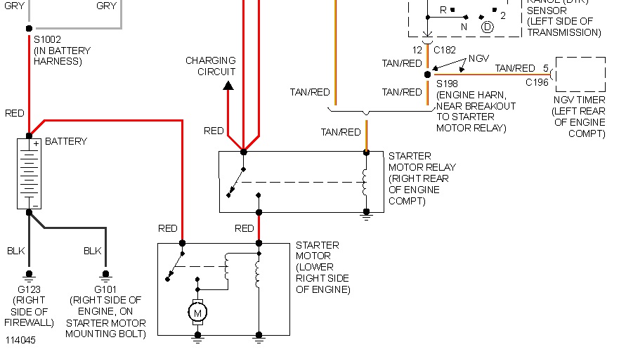
How It Works: The Electrical Path
Here's a simplified explanation of how the starter system operates, as illustrated in the wiring diagram:
- Ignition Switch Activation: When you turn the ignition key to the "Start" position, the ignition switch sends a low-current signal (typically 12V) to the "S" terminal on the starter solenoid.
- Solenoid Activation: This small current energizes the solenoid's internal coil. This coil creates a magnetic field.
- Plunger Engagement: The magnetic field pulls a plunger inside the solenoid, closing heavy-duty contacts.
- High-Current Flow: Closing these contacts allows a very large current to flow directly from the battery (+) to the starter motor. This is the primary function of the solenoid.
- Starter Motor Engagement: The starter motor engages with the flywheel/flexplate, cranking the engine.
- "I" Terminal Functionality: The "I" terminal (Ignition) on some solenoids sends a 12V signal back to the ignition system *during cranking*. This provides a momentary full-voltage boost to the ignition coil to help with starting under load (low battery, cold weather). This is often bypassed, but on a stock system, it will be connected.
Real-World Use: Basic Troubleshooting Tips
Using the wiring diagram, here are some common troubleshooting scenarios:
- Clicking Sound, No Start: This often indicates a weak battery, poor connections, or a failing solenoid. Check battery voltage, clean battery terminals, and verify the ground connections. Use the diagram to check voltage at the solenoid "S" terminal when the key is in the "Start" position. If you have voltage there, but the starter doesn't engage, the solenoid is likely faulty.
- No Sound, No Start: Check the ignition switch, the wiring between the switch and the solenoid, and the solenoid itself. A blown fuse in the starter circuit can also cause this. The wiring diagram is your roadmap for tracing the circuit.
- Starter Stays Engaged: This is a dangerous situation! Immediately disconnect the battery. It often indicates a shorted solenoid or a problem with the ignition switch. A stuck solenoid can overheat the starter motor and potentially cause a fire.
Testing the Solenoid:
- Voltage Test: Use a multimeter to check for 12V at the battery terminal of the solenoid. Then, with the key in the "Start" position, check for 12V at the "S" terminal.
- Continuity Test: Disconnect the battery! Use a multimeter to check for continuity between the battery terminal and the starter motor terminal when the solenoid is activated (have someone turn the key to "Start" while you test). If there's no continuity, the solenoid contacts are likely bad.
Safety First: Highlighting Risky Components
The starter system involves high-current circuits. Working on it can be dangerous if you're not careful. Here are some safety precautions:
- Disconnect the Battery: Always disconnect the negative battery cable before working on any electrical components. This prevents accidental shorts and shocks.
- Wear Safety Glasses: Protect your eyes from sparks and debris.
- Use Insulated Tools: Prevent shocks by using tools with insulated handles.
- Be Aware of Heat: The starter motor and solenoid can get very hot, especially after prolonged cranking. Allow them to cool before touching them.
- Never Bypass the Solenoid: Bypassing the solenoid directly can be extremely dangerous and can damage the starter motor.
- Double Check Connections: Ensure all connections are clean and tight. Loose connections can cause arcing and overheating.
The starter solenoid wiring diagram is an invaluable tool for maintaining and repairing your 1995 Ford F-150's starting system. By understanding the symbols, components, and electrical paths, you can diagnose problems effectively and perform repairs with confidence. Always prioritize safety and double-check your work to ensure reliable operation.
We have the 1995 Ford F150 Starter Solenoid Wiring Diagram file available for download. It is a detailed, high-resolution image that will allow you to easily follow the wiring for your vehicle.