1995 Ford F150 Stereo Wiring Diagram
Understanding the 1995 Ford F150 stereo wiring diagram is crucial for anyone tackling audio system upgrades, repairs, or even just trying to understand the electrical heartbeat of their classic pickup. This guide provides a comprehensive breakdown of the diagram, empowering you to confidently work on your F150's sound system.
Purpose of the Wiring Diagram
The 1995 Ford F150 stereo wiring diagram is a visual roadmap of the audio system's electrical connections. It allows you to:
- Diagnose audio problems: Trace shorts, opens, and incorrect wiring that might be causing issues like no sound, distorted audio, or a non-functional radio.
- Install aftermarket stereos: Safely and correctly connect a new head unit without damaging the factory wiring harness.
- Add amplifiers or speakers: Plan and execute upgrades by understanding the existing circuit and ensuring proper impedance matching.
- Repair damaged wiring: Identify and replace damaged or corroded wires, restoring functionality to the system.
- Learn about automotive electrical systems: Gain a deeper understanding of how the audio system interacts with the vehicle's overall electrical architecture.
Key Specs and Main Parts
Before diving into the diagram, it's helpful to understand the key components involved:
- Head Unit (Radio): The brains of the operation, providing the user interface, signal processing, and often, the amplifier for the speakers. In 1995, these were typically analog units, though some higher trim levels may have incorporated early digital technologies.
- Speakers: Convert electrical signals into audible sound. The F150 typically has speakers in the doors and possibly in the rear of the cab, depending on the cab configuration (e.g., Regular Cab, SuperCab).
- Wiring Harness: A bundle of wires that connects the head unit to the speakers, power source, ground, and other components. The factory harness uses specific connectors to ensure proper connections.
- Antenna: Receives radio signals.
- Power Source: Typically a 12V DC (Direct Current) supply from the vehicle's battery. The radio usually has both a constant 12V wire (for memory) and a switched 12V wire (activated by the ignition).
- Ground: Provides a return path for the electrical current, completing the circuit. A good ground connection is essential for proper operation.
Typical specifications you might encounter when working with the system include:
- Voltage: 12V DC (nominal)
- Speaker Impedance: Usually 4 ohms. Always verify the speaker impedance before connecting aftermarket amplifiers or speakers to avoid damage.
- Wire Gauge: The thickness of the wires, typically specified in AWG (American Wire Gauge). Higher gauge numbers indicate thinner wires.
- Fuse Rating: The current limit of the fuse protecting the circuit. Never replace a fuse with a higher amperage rating, as this can create a fire hazard.
Symbols and Conventions
Wiring diagrams use standardized symbols and conventions to represent electrical components and connections. Understanding these symbols is key to interpreting the diagram effectively.
- Lines: Represent wires. Different colors usually indicate different functions (e.g., red for power, black for ground).
- Dots: Where lines intersect, it indicates a connection. If lines cross without a dot, it means they are not connected.
- Component Symbols: Specific symbols represent various components, such as:
- Resistor: A zigzag line.
- Capacitor: Two parallel lines.
- Ground: A series of horizontal lines decreasing in length.
- Fuse: A wavy line inside a rectangle.
- Speaker: Circle with a cone inside.
- Color Codes: The diagram will use abbreviations for wire colors. Common ones include:
- RD: Red
- BK: Black
- WH: White
- GN: Green
- BL: Blue
- YE: Yellow
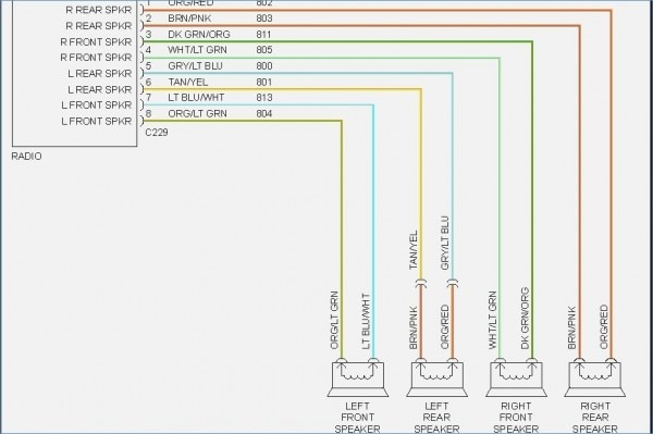
The wiring diagram will also include labels identifying the function of each wire (e.g., "Ignition Switched Power," "Left Front Speaker +").
How It Works: A Simplified Overview
The 1995 F150 stereo system is a relatively simple circuit. Here's a basic overview:
- Power is supplied to the head unit from the battery via a fuse. There are typically two power wires: one constant 12V for memory and one switched 12V that activates when the ignition is turned on.
- When the ignition is turned on, the switched 12V power signal activates the head unit.
- The antenna receives radio signals and sends them to the head unit.
- The head unit processes the radio signals (or plays audio from a cassette or CD player, if equipped).
- The head unit amplifies the audio signal (or sends it to an external amplifier, if present).
- The amplified signal is sent to the speakers via the wiring harness.
- The speakers convert the electrical signal into audible sound.
- All components share a common ground, providing a return path for the current.
Real-World Use: Basic Troubleshooting Tips
Here are some troubleshooting scenarios and how the wiring diagram can help:
- No Power to the Radio:
- Check the fuses associated with the radio (usually located in the fuse panel under the dashboard). The diagram will show you which fuses to check.
- Use a multimeter to test for voltage at the constant and switched 12V wires going to the head unit. If there's no voltage, trace the wire back to the fuse panel, looking for breaks or loose connections.
- Check the ground connection. A loose or corroded ground can cause a variety of problems.
- One Speaker Not Working:
- Check the speaker wiring connections at both the head unit and the speaker itself.
- Use a multimeter to test the speaker wire for continuity (a complete circuit). If there's no continuity, there's a break in the wire.
- Test the speaker itself. You can often use a multimeter to check the speaker's resistance (impedance). A very low or very high reading usually indicates a faulty speaker.
- Distorted Audio:
- Check the speaker wiring for shorts to ground.
- Inspect the speakers for damage.
- If using an external amplifier, ensure the gain is properly adjusted and that the amplifier is not overheating.
Safety Precautions
Working with automotive electrical systems can be dangerous. Always take the following precautions:
- Disconnect the negative battery terminal before working on any electrical components. This prevents accidental shorts and potential electrocution.
- Never work on the electrical system while the engine is running.
- Use proper tools and techniques.
- Never replace a fuse with a higher amperage rating. This can create a fire hazard.
- Be especially careful when working with airbags. Disconnecting the battery for an extended period (check your owner's manual for specific recommendations) is crucial before working near airbag components. Improper handling of airbags can result in serious injury.
- The radio constant power wire remains live even with the ignition off, presenting a shock hazard if mishandled.
The 1995 Ford F150 stereo wiring diagram is your essential tool for navigating the audio system. By understanding the diagram's symbols, conventions, and the system's basic operation, you can confidently diagnose problems, perform upgrades, and keep your classic pickup sounding its best. Remember to always prioritize safety and consult with a qualified technician if you're unsure about any aspect of the repair or installation.
We have the full 1995 Ford F150 stereo wiring diagram available for download. Use it wisely and safely!