1995 Nissan 240sx Fuse Box Diagram
For the experienced DIYer diving into electrical repairs or modifications on a 1995 Nissan 240SX, a reliable fuse box diagram is absolutely essential. It's your roadmap to understanding and troubleshooting the intricate electrical system of this iconic sports car. Whether you're battling a blown fuse, tracing a short circuit, or planning an aftermarket accessory install, this guide will help you decipher the fuse box diagram and use it effectively.
Why You Need This Diagram
A fuse box diagram isn't just a nice-to-have; it's a critical tool for several reasons:
- Troubleshooting Electrical Issues: When something electrical stops working, the fuse box is the first place to look. The diagram pinpoints the fuse responsible for that circuit, saving you hours of aimless probing.
- Understanding Circuit Function: The diagram helps you grasp which components are powered by each fuse, aiding in system-level diagnosis.
- Safe Modification: Adding aftermarket components (like stereos, lights, or alarms) requires careful integration into the existing electrical system. The diagram helps you identify appropriate power sources and fuse ratings.
- Preventing Damage: Replacing a blown fuse with the correct amperage is crucial. Using the wrong fuse can lead to overloading and potential damage to wiring and components.
- Restoration and Repair: For those restoring a 240SX or repairing damaged wiring harnesses, the diagram is invaluable for identifying and tracing circuits.
Key Specs and Main Parts of the Fuse Box
The 1995 Nissan 240SX typically has two primary fuse box locations:
- Interior Fuse Box: Located inside the cabin, usually under the dash on the driver's side. This box houses fuses for interior lights, power windows, radio, and other comfort/convenience features.
- Engine Compartment Fuse Box: Situated in the engine bay, this box protects vital engine and drivetrain components like the fuel pump, ignition system, ECU (Engine Control Unit), and cooling fans.
Key specifications to understand are:
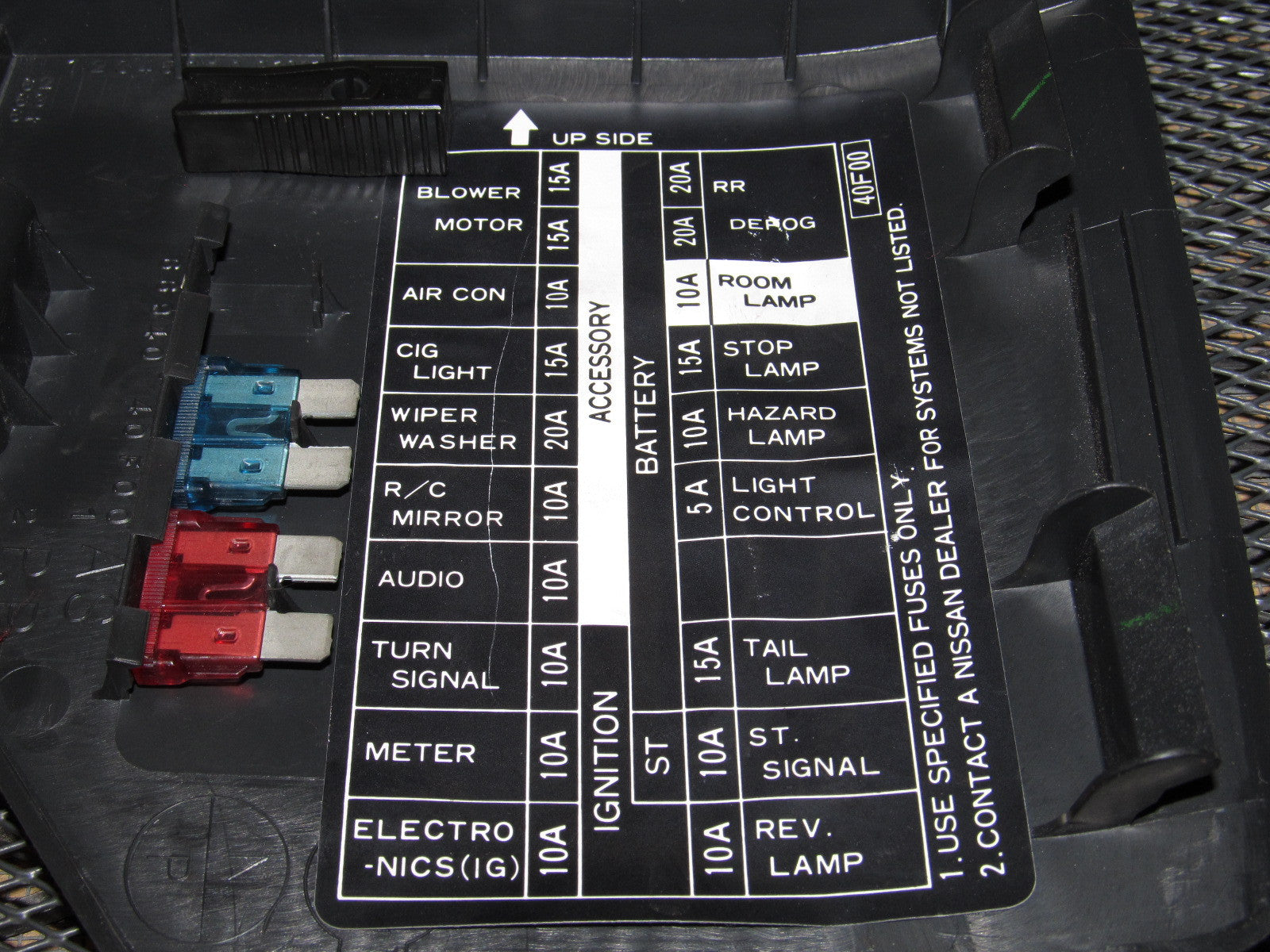
- Fuse Amperage Rating (Amps - A): This indicates the maximum current a fuse can handle before blowing. Common ratings include 5A, 7.5A, 10A, 15A, 20A, 25A, and 30A. Always replace a blown fuse with one of the same amperage.
- Fuse Type: The 1995 240SX typically uses blade-type fuses (also known as spade fuses). These are small, rectangular fuses with two exposed metal terminals.
- Circuit Name/Description: The diagram will label each fuse with a short description of the circuit it protects (e.g., "Tail Lights," "ECU," "Fuel Pump").
- Relays: While not fuses, relays are often located in the fuse box and are essential for controlling high-current circuits like the starter motor, headlights, and fuel pump. The diagram will identify the function of each relay.
Decoding the Symbols
Fuse box diagrams use a variety of symbols and conventions to convey information. Here's a breakdown of common elements:
- Lines: Solid lines represent wires, indicating the path of electrical current. Dashed lines might indicate ground connections or shielded wires.
- Colors: Wire colors are often indicated on the diagram. These colors can be invaluable for tracing wires in the actual harness. Common colors include red (power), black (ground), blue, green, yellow, and white. Understanding the Nissan wire color codes will significantly aid in your troubleshooting.
- Fuse Symbol: A fuse is typically represented by a wavy line or a rectangle with a diagonal line through it. The amperage rating is usually printed next to the symbol.
- Relay Symbol: A relay is represented by a coil symbol and a switch symbol. The coil represents the electromagnet that actuates the switch.
- Ground Symbol: A ground connection is represented by a series of downward-pointing lines or a triangle.
- Component Symbols: The diagram may include simplified symbols representing the components powered by each fuse (e.g., a headlight symbol, a radio symbol, an engine symbol).
How It Works: A Simplified Circuit
Understanding how a basic circuit works will make the fuse box diagram much easier to interpret. Imagine a simple circuit for the tail lights:
- Power flows from the battery (+) through a wire to the fuse box.
- The tail light fuse (e.g., 10A) protects the tail light circuit.
- From the fuse, power flows through a wire to the tail light switch.
- When the switch is turned on, power flows from the switch to the tail lights.
- The tail lights illuminate.
- The circuit is completed by a ground wire connecting the tail lights to the chassis (-), returning the current to the battery.
If there's a short circuit in the tail light wiring (e.g., a wire chafes and touches the chassis), the current draw will increase dramatically. The fuse will blow (the thin wire inside the fuse melts), interrupting the circuit and preventing further damage.
Real-World Use: Basic Troubleshooting
Here's how to use the fuse box diagram for troubleshooting:
- Identify the Problem: What electrical component isn't working? (e.g., the radio, the power windows, the headlights)
- Consult the Diagram: Find the fuse in the diagram that corresponds to the malfunctioning component. The description should clearly indicate its function.
- Locate the Fuse: Find the physical fuse in the fuse box, matching its location to the diagram.
- Inspect the Fuse: Visually inspect the fuse. If the thin wire inside is broken or melted, the fuse is blown.
- Replace the Fuse: Replace the blown fuse with a new fuse of the same amperage rating.
- Test the Circuit: Turn on the component to see if it now works.
- If the Fuse Blows Again: If the new fuse blows immediately, there's likely a short circuit in the wiring or the component itself. Further investigation is needed. This might involve using a multimeter to check for continuity and voltage.
Important Note: If you repeatedly blow fuses, don't just keep replacing them with higher amperage fuses. This is extremely dangerous and can cause a fire. Find and fix the underlying problem.
Safety First
Working with automotive electrical systems can be dangerous. Here are some safety precautions:
- Disconnect the Battery: Before working on the fuse box or any electrical component, disconnect the negative (-) battery terminal to prevent accidental short circuits.
- Use Insulated Tools: Use insulated pliers, screwdrivers, and other tools to avoid electrical shock.
- Be Careful with High-Current Circuits: Circuits like the starter motor and alternator carry high currents and can be dangerous if mishandled.
- Do Not Modify Fuses: Never bypass or modify fuses. They are designed to protect the electrical system and prevent fires. Using a piece of wire or a higher amperage fuse can have disastrous consequences.
- When in Doubt, Consult a Professional: If you're not comfortable working with electrical systems, seek help from a qualified mechanic.
Remember that the ECU (Engine Control Unit) and related engine management systems are particularly sensitive to voltage fluctuations. Incorrect fuse replacements or electrical modifications can potentially damage these components, leading to costly repairs.
With a clear understanding of the 1995 Nissan 240SX fuse box diagram and a cautious approach, you can confidently tackle a wide range of electrical tasks on your vehicle. Remember to always prioritize safety and use the correct tools and procedures.
We have the complete 1995 Nissan 240SX Fuse Box Diagram file available for download. This high-resolution diagram provides clear and detailed information to help you with your electrical projects and repairs.