1996 Ford F250 4x4 Front Hub Assembly Diagram
Alright, let's dive into the 1996 Ford F250 4x4 front hub assembly. This is a system that can seem a bit intimidating at first, but once you understand the components and how they interact, it becomes much more manageable. We're going to break down a typical diagram for this assembly, explaining its purpose, the key components, and how to use it for diagnostics and repairs. Think of me as your experienced mechanic buddy guiding you through the process.
Purpose of the Hub Assembly Diagram
Why bother with a diagram? Well, a detailed hub assembly diagram is essential for a few key reasons:
- Repairs and Maintenance: When you're tackling front-end work like replacing bearings, seals, or the entire hub, the diagram provides a visual roadmap. It shows you the correct order of assembly and the location of each component. Missing a seemingly small part can have significant consequences.
- Troubleshooting: Diagnosing front-end issues, such as noises or vibrations, becomes easier when you can visualize the entire system. The diagram helps you identify potential culprits, like a worn-out wheel bearing or a damaged hub.
- Learning and Understanding: Even if you're not actively working on your truck right now, studying the diagram helps you understand how the 4x4 system functions. This knowledge empowers you to make informed decisions about maintenance and upgrades.
- Part Identification: Need to order a specific part? The diagram typically includes part numbers and clear illustrations that make it easy to identify exactly what you need.
Key Specs and Main Parts
The 1996 Ford F250 4x4 utilizes a Dana 44 or Dana 50 front axle, depending on the specific configuration. Knowing which axle you have is crucial, as some parts are not interchangeable. The hub assembly itself is fairly standardized across these axles, but always double-check part numbers against your VIN.
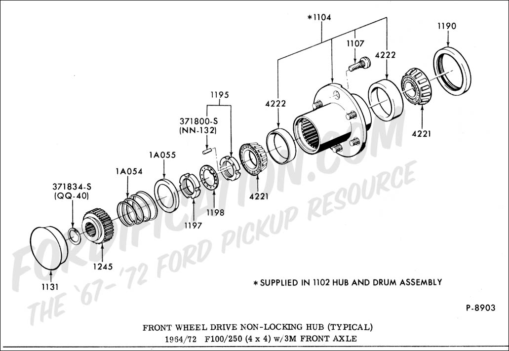
Here are the main components you'll typically find in a hub assembly diagram:
- Wheel Hub: The central component that the wheel mounts to. It rotates on the wheel bearings.
- Wheel Bearings (Inner and Outer): These tapered roller bearings allow the hub to rotate smoothly on the spindle. They're critical for safe operation.
- Wheel Bearing Races (Inner and Outer): These are the hardened steel cups that the wheel bearings sit inside. They are pressed into the hub.
- Spindle: The stationary shaft that the hub rotates around. It's bolted to the steering knuckle.
- Locking Hub Assembly (Manual or Automatic): This mechanism engages or disengages the front axle shafts from the wheels.
- Manual Hubs: Require manual engagement/disengagement by turning a dial.
- Automatic Hubs: Automatically engage/disengage based on vacuum or other mechanical means. (Often problematic and replaced with manual hubs.)
- Axle Shaft: Transmits power from the differential to the wheel (when the hubs are locked).
- Hub Seals (Inner and Outer): Prevent grease from leaking out of the hub and contaminants from entering.
- Grease Cap: Covers the outer end of the hub and protects the outer wheel bearing.
- Spindle Nut(s) and Washer(s): Secure the hub assembly to the spindle and allow for proper wheel bearing preload. Often a two-nut system with a locking tabbed washer.
- Retaining Rings/Snap Rings: Used to hold certain components in place, like the axle shaft in some configurations.
Understanding Diagram Symbols
Hub assembly diagrams, like all technical drawings, use specific symbols to represent different components and their relationships. Here's a breakdown of common symbols:
- Solid Lines: Typically represent solid components, such as the hub, spindle, or bearings.
- Dashed Lines: Often indicate hidden components or lines of sight. For example, a dashed line might show the location of a seal behind the hub.
- Center Lines: Thin, dashed lines with a long and short dash, used to indicate the center of a circular component.
- Arrows: Indicate the direction of force or movement. For example, arrows might show the direction in which to tighten a nut.
- Cross-Sectional Views: Diagrams may include cross-sectional views to show the internal construction of the hub assembly. These views are often shaded or colored to differentiate between different materials.
- Callouts: Numbers or letters with leader lines pointing to specific components, keyed to a parts list.
- Torque Specifications: Often listed near the relevant fastener, indicating the correct tightening torque in ft-lbs or Nm. Always adhere to these specifications!
How It Works (Simplified)
In a nutshell, the hub assembly allows the wheels to rotate freely while also providing a mechanism to connect the front axle shafts for 4x4 operation. Here's the basic flow:
- The wheel is mounted to the hub.
- The hub rotates on the inner and outer wheel bearings, which are supported by the spindle.
- When 4x4 is engaged (either manually or automatically), the locking hub connects the axle shaft to the hub, transmitting power to the wheel.
- When 4x4 is disengaged, the locking hub disconnects the axle shaft, allowing the wheel to rotate freely without being driven by the axle.
Real-World Use: Basic Troubleshooting
Let's say you're hearing a grinding noise coming from your front wheel. Here's how you might use the hub assembly diagram to troubleshoot:
- Consult the Diagram: Identify the components most likely to cause a grinding noise, such as the wheel bearings or the locking hub.
- Visual Inspection: Remove the wheel and inspect the hub assembly for any obvious signs of damage, such as leaking grease, loose components, or worn-out seals.
- Bearing Check: With the wheel removed, try to wiggle the hub. Excessive play indicates worn wheel bearings.
- Hub Function: Check the operation of the locking hub. Ensure it engages and disengages smoothly (if manual) or is functioning correctly if automatic.
- Further Investigation: If the visual inspection doesn't reveal the problem, you may need to disassemble the hub assembly to inspect the bearings and other components more closely. This is where the diagram becomes invaluable for proper reassembly.
Safety Considerations
Working on the hub assembly involves potential risks. Keep these points in mind:
- Wheel Bearings: Worn or damaged wheel bearings can lead to catastrophic failure, resulting in loss of control of the vehicle. Inspect and replace them as needed.
- Springs: If dealing with automatic hubs or related components, be aware that there may be compressed springs. Use caution when disassembling these components.
- Torque Specifications: Always use a torque wrench and adhere to the specified torque values. Over-tightening can damage components, while under-tightening can lead to looseness and failure.
- Proper Support: Always use jack stands to support the vehicle when working underneath. Never rely solely on a jack.
- Brake Components: Be careful not to damage brake lines or other brake components when working on the hub assembly.
- Cleanliness: Keep all components clean during disassembly and reassembly. Contamination can damage bearings and seals.
By understanding the 1996 Ford F250 4x4 front hub assembly diagram, you'll be better equipped to tackle repairs, diagnose problems, and maintain your truck's 4x4 system. Take your time, pay attention to detail, and don't be afraid to ask for help if you get stuck.
We have access to detailed diagrams. These resources are invaluable for anyone undertaking repairs or maintenance on their F250's front hub assembly. These visual aids provide a clear and concise roadmap for disassembly, inspection, and reassembly, ensuring that you don't miss any critical steps or components.