1997 Chevy Silverado Front Suspension Diagram
Let's dive into the front suspension diagram of a 1997 Chevy Silverado. Understanding this diagram is crucial for various reasons, whether you're planning routine maintenance, diagnosing a problem, or even thinking about some performance upgrades. This knowledge will empower you to tackle repairs with confidence and save money in the process.
Why This Diagram Matters
The front suspension diagram is your roadmap to understanding how the Silverado's front end is put together. It’s not just a pretty picture; it’s a vital tool for:
- Troubleshooting: Quickly identify components that might be causing issues like squeaking, clunking, or poor handling.
- Repairs: Ensure you're ordering the correct replacement parts and understand how they fit together.
- Maintenance: Knowing the location of grease fittings and other maintenance points.
- Modifications: Planning upgrades like lift kits or performance shocks.
- General Knowledge: Simply understanding how your truck works!
Key Specs and Main Parts
The 1997 Chevy Silverado, generally speaking, utilizes an independent front suspension system. This means each front wheel can react to road imperfections independently, providing better ride quality and handling compared to a solid axle design. Here’s a breakdown of the key components:
- Upper and Lower Control Arms: These are A-shaped or wishbone-shaped components that connect the wheel hub to the vehicle's frame. They allow the wheel to move up and down while maintaining its alignment.
- Coil Springs: Located between the lower control arm and the frame, these springs absorb bumps and provide support for the vehicle's weight. Some models may use torsion bars instead.
- Shock Absorbers (Dampers): These control the rate at which the suspension moves up and down, preventing excessive bouncing and oscillation. They work by converting kinetic energy into heat through hydraulic fluid.
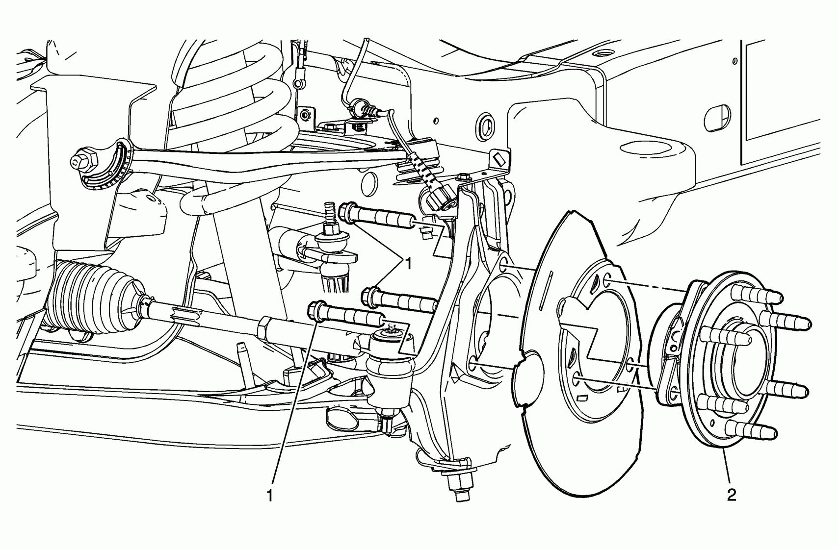
- Spindle (Knuckle): The spindle is the part that the wheel hub and bearing assembly is bolted to. It pivots to allow for steering.
- Wheel Hub and Bearing Assembly: This assembly houses the wheel bearings, which allow the wheel to rotate freely. It's a critical component for smooth and safe operation.
- Tie Rods: These connect the steering rack to the spindles, transferring steering input from the steering wheel to the wheels. There are inner and outer tie rod ends.
- Ball Joints: These are spherical bearings that connect the control arms to the spindle. They allow for movement in multiple planes, essential for steering and suspension articulation.
- Sway Bar (Stabilizer Bar): This bar connects the two front wheels and helps to reduce body roll during cornering.
- Bushings: Rubber or polyurethane bushings are used at various pivot points in the suspension system to dampen vibrations and reduce noise.
Important Notes on Specifications: The exact specifications for components like spring rates, shock absorber valving, and control arm lengths can vary depending on the specific Silverado model (1500, 2500, 3500), engine size, and options package. Always refer to the vehicle's service manual or a reliable parts catalog to ensure you're using the correct specifications for your truck.
Decoding the Diagram: Symbols and Conventions
Understanding the symbols used in the front suspension diagram is essential for interpreting the information it provides. Here are some common conventions:
- Solid Lines: Typically represent rigid components like control arms, spindles, and the frame.
- Dashed Lines: May indicate hidden components or lines that represent movement or travel.
- Arrows: Indicate the direction of force or movement. For example, arrows might show the direction of spring compression or the flow of hydraulic fluid in a shock absorber.
- Circles and Dots: Often represent pivot points, such as ball joints or bushings.
- Labels: Each component will be labeled with its name or a reference number that corresponds to a parts list.
Colors, if present, can also have meaning. While not standardized across all diagrams, some common uses include:
- Blue: May represent hydraulic lines or fluids.
- Red: Might indicate high-stress areas or components requiring special attention.
- Green: Could signify grounding points or electrical connections (though this is more common in electrical diagrams).
How It Works: A Simplified Explanation
The front suspension works in conjunction to provide a smooth and controlled ride. Here's a basic overview:
- When the wheel encounters a bump, the suspension compresses. The coil spring absorbs the energy of the impact, preventing it from being transferred directly to the frame.
- The shock absorber dampens the movement of the spring, preventing it from oscillating excessively.
- The control arms allow the wheel to move up and down while maintaining proper wheel alignment.
- The ball joints allow for the necessary articulation between the control arms and the spindle.
- The tie rods transmit steering input from the steering wheel to the wheels, allowing the driver to control the vehicle's direction.
- The sway bar reduces body roll during cornering by transferring some of the suspension load from one side of the vehicle to the other.
Independent suspension allows each wheel to react to bumps independently. If one wheel hits a pothole, it won't significantly affect the other wheel, leading to a more comfortable and controlled ride. This is unlike a solid axle setup where one wheel's movement directly impacts the other.
Real-World Use: Basic Troubleshooting
Here are some common suspension problems and how the diagram can help you diagnose them:
- Clunking Noise: Could be caused by worn ball joints, loose control arm bushings, or a damaged shock absorber. The diagram helps you locate these components for inspection.
- Squeaking Noise: Often caused by dry ball joints, worn bushings, or a rubbing sway bar link. The diagram will point you to the relevant lubrication points.
- Poor Handling: Can be due to worn shocks, damaged springs, or misaligned suspension components. The diagram helps you identify the parts responsible for maintaining proper alignment.
- Uneven Tire Wear: Could be a sign of worn ball joints, tie rod ends, or misaligned suspension. The diagram helps you understand the relationship between these components and wheel alignment.
Simple Diagnosis Steps: Start by visually inspecting all suspension components for signs of wear, damage, or looseness. Pay close attention to the ball joints, bushings, and shock absorbers. Use the diagram to locate these parts and understand how they connect. If you suspect a specific component is faulty, you can use a pry bar or other tools to check for excessive play. Always prioritize safety when working on suspension components!
Safety First: Handle with Care
The front suspension contains components under significant stress. Springs and torsion bars store a large amount of potential energy, and releasing this energy improperly can cause serious injury. Never attempt to disassemble a suspension system without proper tools and knowledge. If you're unsure about any part of the process, it's best to consult a qualified mechanic.
Specific Safety Precautions:
- Spring Compressors: When removing or installing coil springs, always use a high-quality spring compressor. Follow the manufacturer's instructions carefully.
- Vehicle Support: Always use jack stands to support the vehicle securely before working on the suspension. Never rely solely on a jack.
- Eye Protection: Wear safety glasses to protect your eyes from flying debris.
- Disconnect Battery: Disconnect the negative battery cable to prevent accidental electrical shocks.
By understanding the front suspension diagram and following proper safety procedures, you can confidently tackle repairs and maintenance on your 1997 Chevy Silverado. Remember to consult the vehicle's service manual for specific instructions and torque specifications.
We have a detailed downloadable diagram available for you to use. This resource provides a clear visual representation of the front suspension components and their relationships. Happy wrenching!