
1997 Dodge Ram 1500 Vacuum Line Diagram
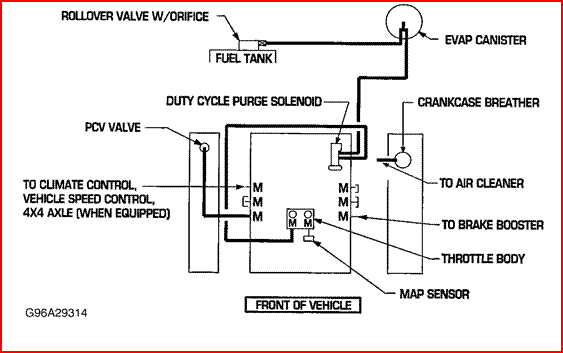
The 1997 Dodge Ram 1500, a workhorse known for its reliability (when properly maintained!), relies heavily on a network of vacuum lines to control various engine and vehicle functions. Understanding the vacuum line diagram for this truck is crucial for anyone attempting repairs, modifications, or even just basic maintenance. This article will guide you through the intricacies of the 1997 Dodge Ram 1500 vacuum system, providing you with the knowledge to confidently diagnose and address vacuum-related issues.
Purpose: Why You Need the Vacuum Line Diagram
Why bother learning about vacuum lines? The simple answer is: troubleshooting. A vacuum leak can manifest in a multitude of ways, from poor engine performance and reduced fuel economy to malfunctioning HVAC systems. A vacuum line diagram acts as a roadmap, allowing you to:
- Identify Components: Locate specific vacuum-operated devices within the engine bay.
- Trace Lines: Follow vacuum lines from source to destination to pinpoint leaks or blockages.
- Understand Connections: Determine the correct routing of vacuum lines after repairs or modifications.
- Diagnose Issues: Relate specific symptoms to potential vacuum system failures.
- Perform Maintenance: Inspect lines for wear and tear as part of routine maintenance.
Whether you're experiencing a rough idle, poor acceleration, or an HVAC system that only blows hot air, a thorough understanding of the vacuum system is paramount. Trying to guess where a line goes or replacing parts without diagnosing the root cause can lead to further complications and wasted money.
Key Specs and Main Parts of the 1997 Dodge Ram 1500 Vacuum System
The 1997 Dodge Ram 1500 typically came with several engine options, including the 3.9L V6, the 5.2L V8 (318 cubic inch), and the 5.9L V8 (360 cubic inch). While the overall vacuum system architecture remains similar across these engines, there might be slight variations in the routing and components. Therefore, always refer to the specific diagram for your engine.
Key components of the vacuum system include:
- Vacuum Source: Manifold vacuum is the primary source. This is the low-pressure area created inside the intake manifold as the engine runs.
- Vacuum Reservoir (Canister): A storage container for vacuum, ensuring a consistent supply even under heavy engine load. Often a black plastic sphere located in the engine bay.
- Vacuum Lines (Hoses): Rubber or plastic hoses that connect various components. These are the arteries and veins of the system. They come in different diameters to accommodate different flow rates.
- Check Valves: One-way valves that allow vacuum to flow in one direction only, preventing pressure backflow.
- Vacuum Switches: Electrical switches activated by vacuum, controlling other circuits.
- EGR Valve (Exhaust Gas Recirculation): Reduces NOx emissions by recirculating exhaust gases into the intake manifold. It is controlled by vacuum.
- PCV Valve (Positive Crankcase Ventilation): Removes harmful crankcase gases and recycles them into the intake manifold.
- HVAC Controls: Vacuum actuators control the blend doors and mode doors within the HVAC system, directing airflow to the desired vents.
- Cruise Control: If equipped, the cruise control system uses vacuum to control the throttle.
Decoding the Vacuum Line Diagram: Symbols, Colors, and Icons
Understanding the symbols used in the vacuum line diagram is crucial for interpreting the information it provides. Here's a breakdown of common elements:
- Lines: Solid lines typically represent vacuum lines, while dashed lines may indicate electrical connections or other related components. The thickness of the line may or may not represent the diameter of the hose.
- Colors: Different colored lines are often used to differentiate vacuum lines based on their function or destination. While the color coding might vary slightly depending on the diagram's source, common colors and their typical meanings include:
- Black: Typically manifold vacuum or a general vacuum source.
- Red: Often used for HVAC-related vacuum lines.
- Green: Can indicate a connection to the EGR valve.
- Yellow: Sometimes used for cruise control related lines.
- Icons: Specific icons represent different components. These may include stylized depictions of the vacuum reservoir, EGR valve, PCV valve, vacuum switches, and actuators. A key or legend accompanying the diagram will define each icon.
Pay close attention to the arrows on the vacuum lines. These indicate the direction of vacuum flow. This is especially important when dealing with check valves, as they only allow flow in one direction.
How the Vacuum System Works: A Simplified Explanation
The engine's intake manifold generates a vacuum when the pistons move down during the intake stroke. This vacuum is the driving force behind the entire system. The manifold vacuum is then distributed through various vacuum lines to different components. For example:
- EGR System: Vacuum applied to the EGR valve diaphragm opens the valve, allowing exhaust gases to flow into the intake manifold.
- HVAC System: Vacuum actuators control doors that direct airflow through the vents. A loss of vacuum to the HVAC system will often result in airflow defaulting to the defrost vents (a safety feature).
- PCV System: The PCV valve regulates the flow of crankcase gases back into the intake manifold.
- Cruise Control: (If equipped) Vacuum is used to actuate the throttle, maintaining a set speed.
The vacuum reservoir acts as a buffer, storing vacuum to ensure a consistent supply, especially during periods of high engine load when manifold vacuum might fluctuate. Check valves prevent backflow, maintaining vacuum in specific circuits.
Real-World Use: Basic Troubleshooting Tips
Here are some basic troubleshooting tips for diagnosing vacuum-related issues:
- Visual Inspection: Start by visually inspecting all vacuum lines for cracks, breaks, or loose connections. Pay close attention to areas near heat sources or where the lines are exposed to friction.
- Vacuum Gauge Test: Use a vacuum gauge to measure manifold vacuum at various points in the system. Low vacuum readings can indicate a leak.
- Smoke Test: A smoke test involves introducing smoke into the vacuum system and observing where it escapes. This is a highly effective method for locating leaks.
- Spray Test: Carefully spray carburetor cleaner or starting fluid around vacuum lines and connections while the engine is running. If the engine's RPM changes, you've likely found a leak in that area. Caution: Carburetor cleaner and starting fluid are flammable. Use sparingly and avoid spraying near hot engine components.
- Component Testing: Test individual vacuum-operated components, such as the EGR valve or HVAC actuators, to ensure they are functioning correctly.
Remember to consult the vacuum line diagram to identify the correct routing and connections for each vacuum line. A small leak can have a significant impact on engine performance.
Safety: Highlighting Risky Components
While working on the vacuum system is generally safe, there are a few potential hazards to be aware of:
- Hot Engine Components: Be careful not to touch hot engine components, such as the exhaust manifold, while working on the vacuum system. Allow the engine to cool down before starting any repairs.
- Flammable Fluids: As mentioned earlier, carburetor cleaner and starting fluid are flammable. Use them sparingly and avoid spraying near hot engine components.
- Vacuum Lines Near Moving Parts: Ensure that vacuum lines are properly secured and routed away from moving parts, such as the fan and belts.
- Battery Disconnect: While not directly vacuum related, disconnecting the battery before starting any repairs can help prevent electrical shocks.
The EGR valve can also be quite dirty due to the exhaust gasses flowing through it. Wear gloves and eye protection when working with it. Also be aware of the potential for asbestos containing gaskets in older vehicles. Take appropriate precautions if disturbing such materials.
By understanding the vacuum system, carefully consulting the diagram, and taking appropriate safety precautions, you can confidently tackle vacuum-related repairs on your 1997 Dodge Ram 1500. Remember to take your time and double-check your work to ensure that all connections are secure.
We have a copy of the 1997 Dodge Ram 1500 Vacuum Line Diagram available for download. Please follow the link below to access the file.
[Link to Download Diagram]