1997 Ford F150 Starter Solenoid Wiring Diagram
So, you're tackling the starter solenoid on your 1997 Ford F150? Good on you! It's a common issue, and understanding the wiring is crucial for diagnosis, repair, or even adding some aftermarket accessories. This article breaks down the 1997 F150 starter solenoid wiring diagram, ensuring you're armed with the knowledge to get the job done right. We'll cover the purpose, specs, symbols, operation, troubleshooting, and, most importantly, the safety aspects.
Purpose of Understanding the Wiring Diagram
Why bother digging into the wiring diagram? Several reasons:
- Troubleshooting Starting Problems: A no-start condition is frustrating. The wiring diagram helps pinpoint whether the issue lies in the ignition switch, the solenoid itself, the wiring in between, or the starter motor.
- Replacing a Faulty Solenoid: Knowing the wiring connections ensures you reconnect everything correctly, preventing damage to other components.
- Adding Accessories: Maybe you want to add a remote start or an anti-theft system. The wiring diagram reveals the necessary connections without resorting to guesswork.
- General Understanding: The diagram provides insight into the starting system's operation, which is invaluable for any experienced DIY mechanic.
Key Specs and Main Parts
Before we dive into the diagram itself, let's establish some fundamental details:
- Vehicle: 1997 Ford F150 (various engine configurations – the basic starting circuit is largely the same)
- System: Starting system
- Voltage: 12V DC (Direct Current) – the standard automotive voltage.
The main components involved in the starting circuit are:
- Battery: Provides the electrical power.
- Ignition Switch: Sends the signal to engage the starter.
- Starter Solenoid: An electromagnetic switch that delivers high current to the starter motor. It's usually mounted on the inner fender well or close to the starter.
- Starter Motor: Cranks the engine.
- Relays & Fuses: Protection devices for the system. There might be fuses related to the starting circuit located in the fuse box(es) of your F150.
- Wiring Harness: Conducts the electrical signals and power.
- Ground Connections: Provides the return path for the electrical current.
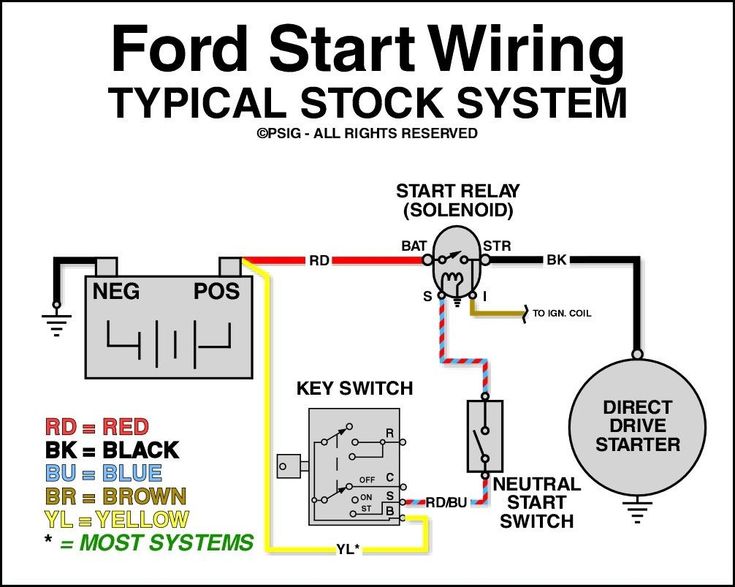
Deciphering the Symbols: Lines, Colors, and Icons
The wiring diagram uses specific symbols to represent components and connections. Here's a breakdown:
- Solid Lines: Indicate wires. Thicker lines usually represent wires carrying higher current.
- Dashed Lines: May indicate a ground connection or a shielded cable.
- Color Codes: Wire colors are crucial. The diagram should list the color abbreviations (e.g., RD for Red, BK for Black, YE for Yellow). Always double-check the wire color against the diagram during repairs.
- Icons:
- Battery: Resembles a series of short and long lines. The '+' symbol indicates the positive terminal, and the '-' symbol indicates the negative terminal (ground).
- Ignition Switch: Shown as a switch with various positions (OFF, ACC, ON, START). The wiring changes depending on the switch position.
- Solenoid: Usually represented by a coil symbol (the electromagnetic coil) and a switch symbol (the high-current contacts).
- Starter Motor: Usually shown as a stylized motor symbol.
- Ground: A series of downward-pointing lines, often resembling a tree.
- Fuse: A zigzag line enclosed in a rectangle.
- Relay: A coil symbol and a switch symbol.
- Splices: A dot where wires connect.
Note: Different diagrams might have minor variations in their symbols. Always refer to the legend or key provided with the specific diagram you are using.
How It Works: The Starting Sequence
Let's walk through the process, following the wiring:
- Turning the Key: When you turn the ignition key to the "START" position, a low-current signal is sent from the ignition switch to the starter solenoid.
- Solenoid Activation: This signal energizes the solenoid's coil. When the coil is energized, it creates a magnetic field.
- Contact Closure: The magnetic field pulls a plunger (or similar mechanism) inside the solenoid. This plunger closes a set of heavy-duty electrical contacts.
- High Current Flow: Closing these contacts completes the circuit between the battery and the starter motor. A very high current (hundreds of amps) flows through these contacts.
- Starter Engages: The starter motor receives the high current and begins to spin, cranking the engine.
- Engine Starts: Once the engine starts, you release the key, the signal to the solenoid is cut off, the contacts open, and the starter disengages.
Real-World Use: Basic Troubleshooting Tips
Here are some common issues and how the wiring diagram can assist you:
- Clicking Sound, No Start: This could indicate a low battery, a faulty starter motor, or a bad solenoid. Use a voltmeter to check the voltage at the solenoid when the key is in the "START" position. If you have voltage at the small signal wire but no voltage at the large wire going to the starter when the solenoid is engaged, the solenoid is likely faulty. Check for good ground connections as well.
- No Sound, No Start: Check the ignition switch, the wiring between the ignition switch and the solenoid, and the solenoid itself. Use a multimeter to check for continuity in the wires and voltage at the solenoid when the key is in the "START" position. Also, check fuses associated with the starting circuit.
- Starter Stays Engaged: This is dangerous! It usually indicates a sticking solenoid. Disconnect the battery immediately to prevent damage to the starter. The solenoid likely needs replacement.
- Blown Fuses: Repeatedly blown fuses in the starting circuit indicate a short circuit. The wiring diagram helps you trace the affected circuit and identify potential locations of the short (e.g., damaged insulation rubbing against metal).
Safety First! Highlighting Risky Components
Working on the starting system involves dealing with high currents and potentially dangerous components:
- Battery: Always disconnect the negative battery terminal before working on the electrical system. This prevents accidental shorts and potential electrical burns.
- High Current Wires: Be extremely careful when handling the heavy-gauge wires connected to the solenoid and starter. They carry a massive amount of current. Ensure they are properly insulated and secured.
- Fuel System: Be mindful of fuel lines near the starter. Accidental sparks could ignite fuel vapors.
- Hot Components: The exhaust manifold and other engine components can be extremely hot. Allow the engine to cool down before working near these areas.
Important Note: If you are uncomfortable working with electrical systems or high currents, consult a qualified mechanic. Incorrect wiring can damage your vehicle and pose a safety risk.
We have the full 1997 Ford F150 starter solenoid wiring diagram available for download. This detailed document will be an invaluable resource as you troubleshoot and repair your truck. Refer to it often, and always prioritize safety.