
1997 Ford F150 Starter Wiring Diagram
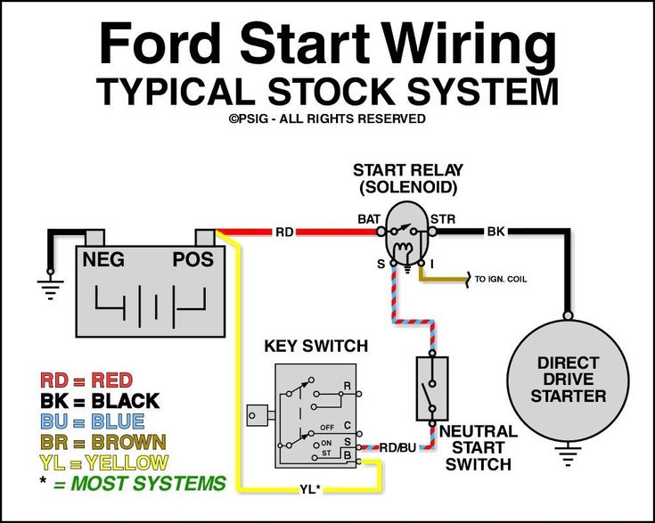
Alright, let's dive into the starter wiring diagram for a 1997 Ford F150. Whether you're dealing with a no-start condition, planning an electrical modification, or just trying to understand how your truck ticks, understanding this diagram is crucial. It's a roadmap of the electrical system responsible for cranking your engine to life.
Purpose of the Starter Wiring Diagram
The starter wiring diagram serves several important purposes:
- Troubleshooting: When your truck won't start, the diagram helps you trace the electrical path to identify faulty components like a bad starter relay, a corroded wire, or a failing starter motor itself.
- Repair: If you need to replace a wire or component in the starter circuit, the diagram shows you exactly where it goes and how it's connected.
- Modification: Planning to add an aftermarket alarm system, remote starter, or kill switch? The diagram is essential for understanding how these modifications will interact with the existing starter circuit.
- Education: Simply understanding the electrical system of your truck can empower you to perform basic maintenance and repairs yourself, saving you money and time.
Key Specs and Main Parts of the 1997 Ford F150 Starter Circuit
Before we get to the diagram itself, let's cover the key components and their specifications. Keep in mind that some details may vary slightly depending on the engine (4.2L V6, 4.6L V8, or 5.4L V8) and specific trim level, but the core principles remain the same.
- Battery: The heart of the electrical system, typically a 12-volt battery with a cold cranking amps (CCA) rating appropriate for the engine size. CCA is crucial for starting in cold weather.
- Battery Cables: Heavy-gauge cables (usually 4-gauge or larger) that carry the high current needed to power the starter motor. The positive (+) cable connects the battery to the starter solenoid, and the negative (-) cable connects the battery to the engine block (ground).
- Starter Solenoid (or Starter Relay): This is an electromagnetic switch that allows a small current from the ignition switch to control a larger current to the starter motor. In the '97 F150, it's often located on the inner fender well, near the battery. This is an electromagnetic switch that closes a circuit with a low current signal from the ignition switch.
- Starter Motor: The heavy-duty electric motor that physically cranks the engine. It has a pinion gear that engages with the flywheel or flexplate to turn the crankshaft.
- Ignition Switch: Located in the steering column, the ignition switch sends a signal to the starter solenoid when you turn the key to the "start" position.
- Neutral Safety Switch (or Transmission Range Sensor): This switch prevents the engine from starting unless the transmission is in Park or Neutral. It's a safety feature to prevent the vehicle from lurching forward or backward during starting.
- Wiring Harness: The collection of wires and connectors that connect all the components in the starter circuit.
- Fuses: Protect the starter circuit from overcurrents. A blown fuse can prevent the starter from working.
Understanding the Symbols in the Diagram
The wiring diagram uses a variety of symbols to represent different components and wires. Here's a breakdown of the most common symbols you'll encounter:
- Solid Lines: Represent wires. The thickness of the line sometimes, but not always, indicates the wire gauge (thicker lines for higher current wires).
- Dashed Lines: Can represent ground connections, shielding, or connections that are not always present.
- Circles: Often represent connection points or splices where multiple wires come together.
- Rectangles: Typically represent components like relays, switches, or control modules. The internal configuration of the rectangle will indicate the type of component.
- Battery Symbol: A series of alternating long and short lines, indicating a DC power source.
- Ground Symbol: Usually a series of downward-pointing lines, indicating a connection to the vehicle's chassis (ground).
- Color Codes: Wires are often color-coded to help identify them. The diagram will usually have a key that lists the color abbreviations (e.g., RD for Red, BLK for Black, WH for White, etc.). Knowing these abbreviations is crucial.
Pay close attention to the wire colors and gauge numbers indicated on the diagram. These are essential for identifying the correct wires when troubleshooting or making repairs.
How the 1997 Ford F150 Starter Circuit Works
The starter circuit works in a relatively straightforward manner:
- When you turn the ignition key to the "start" position, the ignition switch sends a low-current signal to the starter solenoid.
- If the neutral safety switch (or transmission range sensor) is closed (indicating that the transmission is in Park or Neutral), the signal from the ignition switch will reach the starter solenoid.
- The starter solenoid then closes, connecting the battery's positive terminal to the starter motor.
- The starter motor engages, cranking the engine.
- Once the engine starts, you release the ignition key, the signal to the starter solenoid is removed, and the starter motor disengages.
Real-World Use: Basic Troubleshooting Tips
Here are some common issues you might encounter and how the wiring diagram can help you diagnose them:
- No Crank, No Start: Use a multimeter to check for voltage at the starter solenoid when the key is in the "start" position. If there's no voltage, the problem could be the ignition switch, neutral safety switch, or wiring between them. If there is voltage, the solenoid itself might be faulty, or the wiring to the starter motor might be bad.
- Clicking Noise, No Start: This often indicates a weak battery or poor connections to the starter motor. Check the battery voltage and clean the battery terminals and cable connections. If those are good, the starter motor itself might be failing.
- Starter Motor Runs, But Engine Doesn't Crank: This suggests that the starter motor pinion gear is not engaging with the flywheel or flexplate. The starter motor might be faulty, or the flywheel/flexplate might be damaged.
- Blown Fuses: Repeatedly blown fuses indicate a short circuit in the starter circuit. Use the wiring diagram to trace the circuit and identify the source of the short.
Always use a multimeter to safely test circuits. Never rely on visual inspection alone.
Safety Precautions
Working on the starter circuit involves dealing with high currents, so it's crucial to take the following safety precautions:
- Disconnect the Battery: Always disconnect the negative (-) battery cable before working on the electrical system. This will prevent accidental short circuits and electrical shocks.
- Wear Safety Glasses: Protect your eyes from sparks and debris.
- Use Insulated Tools: Use tools with insulated handles to prevent electrical shocks.
- Be Aware of Hot Components: The starter motor and exhaust manifold can get very hot, so be careful not to burn yourself.
- Specifically, be careful of the starter solenoid terminals. Accidental contact with a wrench to ground will cause a huge spark and potential damage.
Remember: When in doubt, consult a qualified mechanic. Electrical problems can be complex and dangerous, and it's always better to be safe than sorry.
We have a detailed 1997 Ford F150 starter wiring diagram file available for download. This document provides a visual reference and will be very helpful as you work on your car. Consult your repair manual for additional support.