1997 Ford Ranger 2.3 Spark Plug Wire Diagram
Let's dive into the spark plug wire diagram for a 1997 Ford Ranger with the 2.3L engine. This article aims to provide a comprehensive understanding of the diagram, enabling you to perform diagnostics, repairs, and even enhance your understanding of this classic engine. Having a clear understanding of this diagram is crucial for troubleshooting ignition problems, replacing faulty components, and ensuring optimal engine performance. This knowledge will save you money on mechanic bills and empower you to tackle these tasks yourself.
Purpose of the Spark Plug Wire Diagram
The spark plug wire diagram for your '97 Ranger 2.3L serves as a roadmap for the engine's ignition system. It visually represents the connection between the ignition coil (or distributor, depending on your specific engine configuration) and the spark plugs. This diagram is vital for:
- Troubleshooting Ignition Issues: Pinpointing misfires, rough idling, and starting problems.
- Replacing Spark Plug Wires: Ensuring correct wire routing to prevent crossfiring and engine damage.
- Understanding Engine Firing Order: Grasping the sequence in which the cylinders ignite, crucial for advanced diagnostics.
- Verifying Component Integrity: Checking the electrical path from the coil to the spark plugs.
Key Specs and Main Parts
Before we dive into the diagram itself, let's quickly review the key components it depicts:
- Spark Plugs: These are the electrodes that ignite the air-fuel mixture in each cylinder. They require high voltage to create a spark.
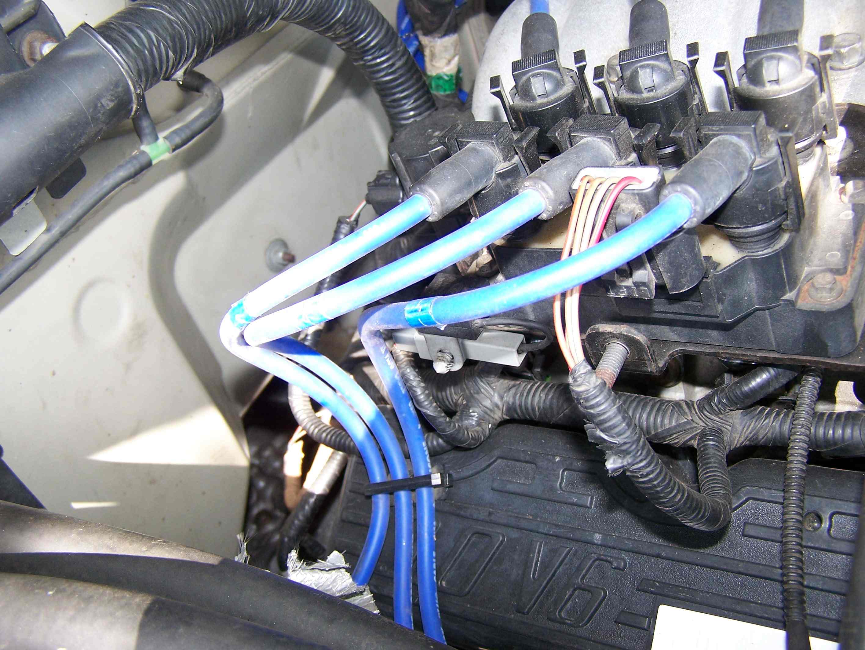
- Spark Plug Wires: These high-tension wires carry the high-voltage pulses from the ignition coil to the spark plugs.
- Ignition Coil (or Distributor): This component is responsible for generating the high voltage required to fire the spark plugs. Some '97 Ranger 2.3L engines may have a distributor-less ignition system (DIS) with multiple coils.
- Firing Order: The sequence in which the cylinders ignite. For the 2.3L Ranger, the firing order is typically 1-3-4-2.
The firing order is critically important. Incorrectly connecting the spark plug wires will result in severe engine misfires and potential damage.
Symbols and Conventions Explained
Understanding the symbols and conventions used in the diagram is key to its interpretation. Here's a breakdown:
- Solid Lines: Represent the spark plug wires themselves, indicating a physical electrical connection.
- Numbers: Correspond to the cylinder numbers (typically 1 through 4 for a 2.3L inline-four engine). These numbers may be shown at the spark plug end of the wires and/or at the coil terminals.
- Coil/Distributor Terminals: Labeled with numbers or letters corresponding to the cylinders they serve (e.g., terminal "1" on the coil connects to cylinder #1). For a DIS system, each coil will be labeled according to the cylinders it serves (e.g., a coil labeled "1-4" fires cylinders 1 and 4).
- Color Coding (Optional): Some diagrams may use different colored lines to represent different wires. This isn't always present, but if it is, a legend should accompany the diagram.
The diagram may also include symbols for grounding points and other related electrical components. These are typically represented with standard electrical symbols you can find online or in a basic automotive wiring guide.
How It Works: The Ignition System in Brief
The '97 Ranger 2.3L ignition system, in simplified terms, works as follows:
- The engine control module (ECM) signals the ignition module (or directly controls the coil in a DIS system) to fire.
- The ignition coil transforms the 12-volt battery voltage into a high-voltage pulse (typically 20,000-40,000 volts).
- This high-voltage pulse travels through the spark plug wire to the corresponding spark plug.
- At the spark plug, the voltage jumps the gap between the center electrode and the ground electrode, creating a spark.
- This spark ignites the air-fuel mixture in the cylinder, initiating the combustion process.
The timing of this process is precisely controlled by the ECM to ensure optimal engine performance and fuel efficiency.
Real-World Use: Basic Troubleshooting Tips
Here are a few practical ways to use the spark plug wire diagram for troubleshooting:
- Misfire Diagnosis: If you suspect a misfire in a particular cylinder (e.g., cylinder #3), use the diagram to trace the spark plug wire back to the coil terminal. Inspect the wire for damage, cracks, or loose connections. You can also swap the wire with another cylinder's wire to see if the misfire follows the wire.
- Wire Replacement: When replacing spark plug wires, use the diagram as a reference to ensure you connect the new wires in the correct order. Connect one wire at a time to avoid confusion.
- Crossfire Prevention: Ensure the spark plug wires are routed properly, away from each other and from hot engine components. Crossfiring (where the spark jumps from one wire to another) can cause severe misfires. Use wire separators to keep the wires organized.
- Visual Inspection: Periodically inspect the spark plug wires for signs of wear and tear, such as cracks, burns, or fraying. Replace damaged wires promptly.
If you have access to an oscilloscope, you can use it to analyze the spark waveform and diagnose more complex ignition problems. This requires advanced knowledge and training, however.
Safety Precautions
Working with the ignition system involves high voltage, which can be dangerous. Observe the following safety precautions:
- Never work on the ignition system with the engine running.
- Disconnect the negative battery cable before working on any electrical components.
- Use insulated tools when working near high-voltage components.
- Avoid touching spark plug wires or the ignition coil while the engine is cranking or running.
- Be aware that capacitors in the ignition system can store a charge even after the engine is turned off. Allow time for the capacitors to discharge before touching any components.
The ignition coil is particularly risky due to the high voltage it generates. Exercise extreme caution when working near it.
Always double-check your work and consult a qualified mechanic if you are unsure about any aspect of the repair. Safety should always be your top priority.
We have a downloadable PDF file that contains a detailed spark plug wire diagram specifically for the 1997 Ford Ranger with the 2.3L engine. You can access this file by [link to download]. This diagram will provide a visual aid to help you with troubleshooting and repairs.