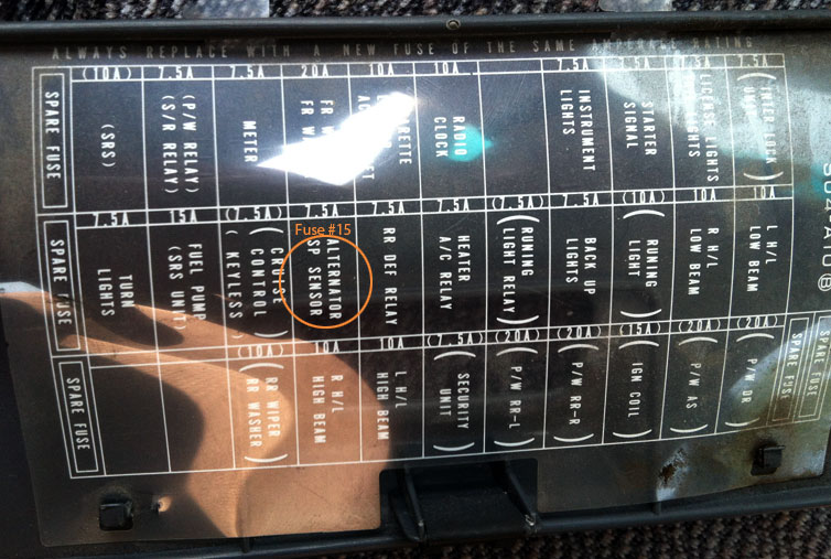
1997 Honda Civic Interior Fuse Box Diagram
The interior fuse box in your 1997 Honda Civic is a critical component for electrical system protection and troubleshooting. Whether you're facing a blown fuse, planning to install aftermarket accessories, or simply want a better understanding of your car's electrical infrastructure, having a clear and accurate fuse box diagram is essential. This article provides a comprehensive guide to understanding the 1997 Honda Civic interior fuse box diagram, empowering you to diagnose and resolve electrical issues with confidence.
Purpose of Understanding the Fuse Box Diagram
Why bother with a fuse box diagram? Several compelling reasons make this knowledge invaluable:
- Electrical Repairs: When electrical components malfunction – a dome light that won't turn on, a malfunctioning radio, or a non-operational power window – the first step is often to check the corresponding fuse. A diagram ensures you're checking the correct fuse, saving time and preventing accidental tampering with unrelated circuits.
- Accessory Installation: Adding aftermarket components like stereos, alarms, or lighting requires tapping into the car's electrical system. The diagram helps you identify appropriate power sources and choose suitable fuse ratings to protect the new accessory and the car's existing wiring.
- Understanding Vehicle Systems: The fuse box diagram is essentially a roadmap of the car's electrical system. Studying it provides insights into how different components are powered and protected, fostering a deeper understanding of your vehicle.
- Preventing Electrical Fires: Fuses are designed to protect wiring from overload. Using the correct amperage fuse, as specified in the diagram, is critical to preventing potentially dangerous electrical fires. Replacing a blown fuse with one of a higher amperage is a serious safety hazard and should NEVER be done.
Key Specs and Main Parts of the 1997 Civic Interior Fuse Box
The interior fuse box in the 1997 Honda Civic is typically located under the dashboard on the driver's side, often behind a small access panel. It houses an array of fuses, each protecting a specific circuit. Key components include:
- Fuses: These are the sacrificial components that protect electrical circuits. They contain a thin wire that melts and breaks the circuit when excessive current flows through it, preventing damage to components. Fuses are rated in amperes (amps or A), indicating the maximum current they can handle before blowing.
- Relays: Relays are electromechanical switches that allow a low-current circuit to control a high-current circuit. They are used to power components that require significant current, like headlights or the starter motor. While the interior fuse box primarily houses fuses, some relays related to interior functions may be present.
- Fuse Puller: A small plastic tool used to safely remove and install fuses without damaging them.
- The Fuse Box Diagram: Usually a sticker located on the inside of the fuse box cover or in the owner's manual, this diagram is your key to understanding the function of each fuse.
Typical fuse amperage ratings found in the interior fuse box range from 5A to 30A, but this can vary slightly depending on the specific trim level and options installed in your Civic.
Decoding the Symbols on the Fuse Box Diagram
Fuse box diagrams use standardized symbols and abbreviations to represent different components and their functions. Understanding these symbols is crucial for interpreting the diagram correctly.
- Lines: Solid lines typically represent electrical wiring. Dashed lines may indicate ground connections or shielded wiring.
- Colors: Wire colors are often indicated on the diagram using abbreviations (e.g., "BLU" for blue, "RED" for red, "GRN" for green). Identifying wire colors can be helpful when tracing circuits.
- Icons: Specific icons represent different components. Common icons include:
- Headlight Icon: Indicates a fuse related to the headlights.
- Radio Icon: Indicates a fuse related to the radio.
- Cigarette Lighter Icon: Indicates a fuse related to the cigarette lighter/accessory power outlet.
- Wiper Icon: Indicates a fuse related to the windshield wipers.
- Horn Icon: Indicates a fuse related to the horn.
- Amperage Rating: Each fuse location on the diagram will be labeled with the correct amperage rating for that fuse. This is often displayed as a number followed by "A" (e.g., "10A").
Some diagrams may also include abbreviations for the circuit being protected (e.g., "IGN" for ignition, "ACC" for accessory).
How It Works: The Fuse Box as a Circuit Protection Hub
The fuse box acts as the central distribution point for electrical power within your Civic. Power from the battery flows through the ignition switch and other control modules before reaching the fuse box. From there, it's distributed to various circuits, each protected by its own fuse.
When a short circuit or overload occurs in a particular circuit, the excessive current causes the fuse to blow, interrupting the flow of electricity and preventing damage to the wiring and components in that circuit. The fuse essentially acts as a safety valve, sacrificing itself to protect the more expensive and critical components.
Relays, when present in the interior fuse box, function as remote-controlled switches. A small current from the ignition switch or another control module activates the relay, which then closes a circuit that allows a larger current to flow to a component like the rear window defogger. This allows the use of smaller gauge wiring for the control circuit, saving weight and cost.
Real-World Use: Basic Troubleshooting Tips
Here's how you can use the fuse box diagram to troubleshoot common electrical issues:
- Identify the Symptom: What component isn't working? (e.g., dome light, radio, power windows).
- Consult the Diagram: Locate the fuse that corresponds to the malfunctioning component. Refer to the diagram to identify the correct fuse location and amperage rating.
- Inspect the Fuse: Carefully remove the fuse using a fuse puller. Examine the fuse element. If the wire is broken or blackened, the fuse is blown.
- Replace the Fuse: Replace the blown fuse with a new fuse of the same amperage rating. Never use a fuse with a higher amperage rating.
- Test the Circuit: Turn on the affected component to see if it now works.
- If the Fuse Blows Again: If the new fuse immediately blows, there is likely a short circuit or other problem in the circuit. Further diagnosis is required, potentially involving a multimeter and wiring diagrams. Consider consulting a qualified mechanic.
Safety Precautions When Working with the Fuse Box
Working with electrical systems can be dangerous. Adhere to these safety precautions:
- Disconnect the Battery: Before working on the fuse box, disconnect the negative terminal of the battery to prevent accidental short circuits. This is especially important if you're working near the main power distribution block.
- Use the Correct Fuse Rating: Always replace a blown fuse with a fuse of the same amperage rating. Using a higher amperage fuse can overload the wiring and cause a fire.
- Avoid Wet Conditions: Never work on the fuse box in wet or damp conditions. Water can conduct electricity and create a shock hazard.
- Beware of High-Current Circuits: Some circuits, such as those related to the starter motor or the alternator, carry high currents. Be especially cautious when working near these circuits. The starter and alternator circuits are generally located in the engine bay fuse box, but be aware that the interior fuse box may have some connected circuits.
- Don't Overload Circuits: When adding aftermarket accessories, ensure that you're not overloading existing circuits. Calculate the total current draw of all components on the circuit and choose a fuse rating that can handle the load safely. It's almost always best to wire aftermarket accessories directly to the battery using a dedicated fuse and wiring harness.
Disclaimer: This article provides general guidance only. Consult the official 1997 Honda Civic service manual for specific instructions and safety precautions. If you're not comfortable working with electrical systems, consult a qualified mechanic.
We have a downloadable version of the 1997 Honda Civic interior fuse box diagram for your convenience. You can access it [Link to Download - Placeholder, insert the actual link here]. Having this diagram readily available will be invaluable during troubleshooting and electrical modifications.