
1997 Nissan Pickup Coolant Hose Diagram
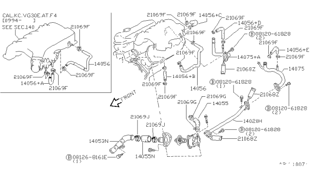
The cooling system in your 1997 Nissan Pickup is a critical component for ensuring the engine runs efficiently and prevents overheating. Understanding the coolant hose diagram is essential for performing maintenance, troubleshooting problems, or even undertaking engine modifications. This guide provides a detailed look at the coolant hose system in the 1997 Nissan Pickup, offering insights that even experienced DIY mechanics will find valuable.
Purpose of the Coolant Hose Diagram
The coolant hose diagram serves several crucial purposes:
- Repair and Maintenance: Identifying the correct hoses for replacement during routine maintenance (e.g., when hoses become brittle, cracked, or leaky) is paramount.
- Troubleshooting Overheating: The diagram helps diagnose cooling system issues. Tracing coolant flow allows you to pinpoint clogs, leaks, or malfunctioning components like the thermostat or water pump.
- Engine Modifications: If you're modifying your engine (e.g., adding a turbocharger or performing an engine swap), understanding the coolant system's layout is essential for routing new hoses and integrating aftermarket cooling components.
- Learning the System: Simply understanding how the cooling system works provides a deeper understanding of engine operation and its overall health.
Key Specs and Main Parts of the 1997 Nissan Pickup Cooling System
The 1997 Nissan Pickup came with several engine options, primarily the KA24E (2.4L SOHC 4-cylinder) and the VG30E (3.0L SOHC V6). The coolant hose layout varies slightly between these engines, but the fundamental principles remain the same. Here's a breakdown of the main components and key specifications related to the coolant hoses:
- Radiator: This is the primary heat exchanger, dissipating heat from the coolant as air flows through its fins. It's connected to the engine via the upper and lower radiator hoses. The radiator typically has a pressure cap to maintain system pressure.
- Water Pump: The water pump, driven by the engine's accessory belt, circulates coolant throughout the system. It's usually located at the front of the engine.
- Thermostat: The thermostat regulates engine temperature by controlling the flow of coolant to the radiator. It opens and closes based on coolant temperature.
- Upper Radiator Hose: Connects the engine (typically near the thermostat housing) to the top of the radiator. This hose carries hot coolant away from the engine.
- Lower Radiator Hose: Connects the bottom of the radiator to the water pump. This hose carries cooled coolant back to the engine. It often contains a spring to prevent collapse under vacuum.
- Heater Hoses: Small-diameter hoses that circulate coolant through the heater core in the passenger compartment, providing heat.
- Bypass Hose (if equipped): A smaller hose that allows coolant to circulate within the engine block when the thermostat is closed, preventing localized overheating.
- Overflow Tank (Coolant Reservoir): A plastic container that allows for coolant expansion and contraction as the engine heats up and cools down. Connected to the radiator neck via an overflow hose.
- Hose Clamps: Secure the hoses to the various components. Typically, these are either spring clamps or screw clamps.
Key Specifications: The coolant system capacity is typically around 7-8 quarts (depending on the engine). The recommended coolant is usually a green ethylene glycol-based antifreeze mixed with distilled water in a 50/50 ratio. Refer to your owner's manual for the exact coolant specification for your specific engine.
Understanding the Symbols in the Coolant Hose Diagram
A coolant hose diagram isn't just a picture; it uses specific symbols to represent different components and flow paths. Here's a breakdown:
- Lines: Solid lines typically represent coolant hoses. Dashed lines may indicate vacuum lines or other components not directly involved in the coolant flow.
- Arrows: Arrows indicate the direction of coolant flow. Pay close attention to these arrows to understand how the coolant circulates through the system.
- Colors: Some diagrams use colors to differentiate between hoses or identify hot versus cold coolant lines. For example, red might indicate hot coolant exiting the engine, while blue might indicate cooled coolant returning to the engine. However, color-coding isn't universal.
- Component Icons: Icons represent specific components like the radiator, water pump, thermostat housing, and heater core. These icons are often simplified representations of the actual parts.
A good diagram will also include labeled components. Look for abbreviations like "Rad" for radiator, "WP" for water pump, "TH" for thermostat housing, and "HC" for heater core.
How the Cooling System Works
Understanding the basic operation of the cooling system is key to interpreting the hose diagram effectively.
- The water pump circulates coolant from the bottom of the radiator, through the engine block, and into the cylinder head.
- As coolant passes through the engine, it absorbs heat generated by combustion.
- The hot coolant then flows through the upper radiator hose to the radiator.
- Within the radiator, heat is dissipated into the atmosphere as air flows across the radiator fins.
- Cooled coolant exits the radiator through the lower radiator hose and returns to the water pump, completing the cycle.
- The thermostat regulates the flow of coolant to the radiator. When the engine is cold, the thermostat remains closed, restricting coolant flow to the radiator and allowing the engine to warm up quickly. A bypass hose usually provides some limited coolant circulation within the engine when the thermostat is closed.
- Once the engine reaches its operating temperature, the thermostat opens, allowing coolant to flow to the radiator and maintain a stable engine temperature.
- The heater core receives hot coolant from the engine, which is then used to heat the passenger compartment.
Real-World Use and Basic Troubleshooting
Here's how to use the coolant hose diagram for troubleshooting common issues:
- Locating Leaks: If you suspect a coolant leak, use the diagram to identify all potential leak points (hose connections, radiator, water pump, heater core). Inspect each hose and connection for signs of coolant residue or corrosion.
- Diagnosing Overheating: If your engine is overheating, the diagram can help you isolate the problem. Check the thermostat housing and radiator hoses. If the upper radiator hose is hot but the lower radiator hose is cold, the thermostat may be stuck closed. If both hoses are relatively cool, the water pump may be malfunctioning.
- Replacing Hoses: When replacing a coolant hose, use the diagram to ensure you're replacing the correct hose with the correct part. Carefully disconnect the old hose and install the new hose, securing it with new hose clamps.
- Flushing the System: The diagram helps you understand where to connect a flush kit to properly circulate cleaning solution through the entire system. Disconnect the upper or lower radiator hose (depending on kit instructions) and connect the flush kit inline.
Safety Considerations
Working with the cooling system can be dangerous. Observe the following safety precautions:
- Never open the radiator cap when the engine is hot. The system is pressurized, and hot coolant can erupt, causing severe burns. Wait until the engine has cooled down completely before opening the cap.
- Wear safety glasses to protect your eyes from splashes of coolant.
- Coolant is toxic. Avoid skin contact and ingestion. Clean up any spills immediately. Dispose of used coolant properly at a recycling center.
- Be careful when working around the water pump pulley and accessory belt. Ensure the engine is off and the key is removed before working in this area.
- The thermostat housing can be a particularly risky component to handle when hot.
Remember to always consult your vehicle's service manual for specific procedures and torque specifications.
We have a downloadable version of the 1997 Nissan Pickup Coolant Hose Diagram for both the KA24E and VG30E engines. This diagram provides a clear visual reference for all the hoses and components discussed in this article. You can use this diagram to better understand the cooling system and troubleshoot any potential problems. Please contact us to receive the file.