1997 Toyota 4runner Fuse Box Diagram
The 1997 Toyota 4Runner, a rugged and reliable SUV, is a popular choice for both daily drivers and off-road enthusiasts. Understanding its electrical system is crucial for maintenance, repairs, and modifications. This article will provide a detailed breakdown of the 1997 4Runner's fuse box diagram, offering the insights needed to diagnose electrical issues and perform basic troubleshooting. We'll explain the purpose of the diagram, key components, symbols, how the system works, real-world uses, safety precautions, and how to access a downloadable version of the diagram.
Why This Diagram Matters: The Heart of Your 4Runner's Electrical System
The fuse box diagram is essentially a roadmap to your 4Runner's electrical system. It's invaluable for several reasons:
- Troubleshooting Electrical Problems: When a component stops working (e.g., a taillight, the radio, or the power windows), the first place to check is the fuse box. The diagram identifies the specific fuse associated with that circuit, allowing you to quickly determine if a blown fuse is the culprit.
- Performing Repairs: Knowing the location and function of each fuse and relay is essential when repairing wiring issues or replacing electrical components.
- Adding Accessories: If you're installing aftermarket accessories like lights, amplifiers, or alarms, the fuse box diagram helps you identify suitable power sources and protect the new circuitry with appropriate fuses.
- Understanding Your Vehicle: Even if you're not actively working on your 4Runner, understanding the fuse box layout provides a general understanding of how its electrical system is organized.
Key Specs and Main Parts of the Fuse Box
The 1997 4Runner has two primary fuse box locations:
- Interior Fuse Box: Located under the dashboard, typically on the driver's side. This box houses fuses and relays for interior components like the radio, lights, power windows, and wipers.
- Engine Compartment Fuse Box: Situated near the engine, usually on the driver's side. This box contains fuses and relays for engine-related components like the fuel pump, ignition system, and cooling fan.
Key Components:
- Fuses: Fuses are safety devices designed to protect electrical circuits from overcurrent. They contain a thin wire that melts and breaks the circuit if the current exceeds a certain limit. Fuses are rated in amperes (amps), indicating the maximum current they can handle. Common fuse types include blade fuses (ATO/ATC) and mini blade fuses.
- Relays: Relays are electromechanical switches that control high-current circuits using a low-current signal. They allow a small switch (e.g., a headlight switch) to control a powerful device (e.g., the headlights) without having to route high current through the switch itself.
- Circuit Breakers: Circuit breakers are similar to fuses but can be reset after tripping. They are often used in circuits that are prone to temporary overloads.
- Fuse Puller: A small plastic tool designed to safely remove fuses from the fuse box.
Decoding the Symbols and Legends
The fuse box diagram uses a variety of symbols to represent different components and circuits. Understanding these symbols is crucial for interpreting the diagram correctly. Here's a breakdown of some common symbols:
- Lines: Solid lines represent wires, while dashed lines may indicate grounding points or connections.
- Boxes: Boxes typically represent fuses, relays, or circuit breakers.
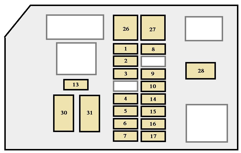
- Numbers: Numbers inside or near the boxes indicate the fuse or relay number and its amperage rating (for fuses).
- Icons: Small icons are used to represent the function of the circuit protected by the fuse or controlled by the relay. Common icons include:
- Headlight Icon: Indicates the headlight circuit.
- Windshield Wiper Icon: Indicates the windshield wiper circuit.
- Radio Icon: Indicates the radio circuit.
- Power Window Icon: Indicates the power window circuit.
- Engine Icon: Indicates an engine-related circuit.
- Colors: Wire colors are often indicated on the diagram using abbreviations (e.g., "BLU" for blue, "RED" for red, "BLK" for black). These colors correspond to the actual wire colors in the vehicle.
Example: A box labeled "15A H-LP" with a headlight icon indicates a 15-amp fuse protecting the headlight circuit. Knowing the color of the wire connected to that fuse can help you trace the circuit if you need to diagnose a wiring problem.
How the Fuse Box System Works: Protecting the Electrical Backbone
The fuse box acts as a central distribution point for electrical power throughout your 4Runner. Power from the battery is routed to the fuse boxes, where it's then distributed to various circuits via fuses and relays. Each fuse protects a specific circuit from overcurrent. If a short circuit or excessive current draw occurs in a particular circuit, the fuse will blow, interrupting the flow of electricity and preventing damage to the wiring and components connected to that circuit.
Relays, on the other hand, allow low-current switches to control high-current devices. For example, when you turn on your headlights, the headlight switch activates a relay that then connects the headlights to the battery. This prevents the headlight switch from having to handle the high current required to power the headlights, which could damage the switch.
The fuse box diagram shows the location of each fuse and relay, its function, and its amperage rating (for fuses). This information allows you to quickly identify and replace blown fuses, diagnose electrical problems, and add new accessories to your 4Runner's electrical system.
Real-World Use: Basic Troubleshooting Tips
Here are some basic troubleshooting tips using the fuse box diagram:
- Symptom: A specific electrical component is not working (e.g., a taillight).
- Step 1: Consult the fuse box diagram to identify the fuse associated with that component.
- Step 2: Locate the fuse in the fuse box.
- Step 3: Visually inspect the fuse. A blown fuse will typically have a broken wire inside.
- Step 4: If the fuse is blown, replace it with a new fuse of the same amperage rating. Never use a fuse with a higher amperage rating, as this could damage the wiring and components.
- Step 5: Test the component to see if it is now working. If the fuse blows again immediately, there is likely a short circuit in the wiring or the component itself.
- Symptom: The engine won't start.
- Step 1: Check the fuses for the fuel pump, ignition system, and starter motor.
- Step 2: If any of these fuses are blown, replace them.
- Step 3: If the engine still won't start, there may be other issues, such as a faulty fuel pump, ignition module, or starter motor.
Safety Precautions: Respecting the Electrical System
Working with your 4Runner's electrical system can be dangerous if you're not careful. Here are some important safety precautions:
- Disconnect the Battery: Before working on any electrical components, always disconnect the negative (-) battery cable to prevent accidental shorts and electrical shocks.
- Use the Correct Fuses: Never replace a fuse with one of a higher amperage rating. This could overload the circuit and cause a fire. Always use fuses with the specified amperage rating.
- Be Careful with High-Current Circuits: Circuits like the starter motor and alternator carry high currents. Avoid touching these components while the engine is running or the ignition is on.
- Avoid Working in Wet Conditions: Water and electricity don't mix. Avoid working on the electrical system in wet or damp conditions.
- Be Aware of Airbags: Airbag systems have their own dedicated fuses. Exercise extreme caution when working near airbag components. Consult the service manual for specific instructions. Accidental deployment of an airbag can cause serious injury.
Diagram Availability
Having the actual fuse box diagram readily available is essential. Because of variances across production runs and specific model options, having the precise diagram for your specific 1997 4Runner is crucial.
We have compiled the 1997 Toyota 4Runner fuse box diagram for both the interior and engine compartment fuse boxes. This document contains detailed information about each fuse and relay, including its location, function, and amperage rating. You can download this diagram now by [Link to Download].
By understanding and utilizing this information, you'll be better equipped to maintain, repair, and modify your 1997 Toyota 4Runner, ensuring its reliability and performance for years to come.