1998 Chevy Silverado Wiring Harness Diagram
Let's dive into the 1998 Chevy Silverado wiring harness diagram. Whether you're tackling a repair, installing aftermarket accessories, or simply trying to understand your truck better, a wiring diagram is an invaluable resource. Think of it as a roadmap for your Silverado's electrical system, guiding you through the intricate network of wires and components.
Purpose of the Wiring Harness Diagram
Why bother with a wiring diagram? Well, imagine trying to fix a short circuit without one. You'd be poking around blindly, likely making things worse! A diagram provides a clear visual representation of the electrical system, enabling you to:
- Diagnose electrical issues accurately: Pinpoint the exact location of a fault, whether it's a blown fuse, a broken wire, or a malfunctioning sensor.
- Perform repairs efficiently: Avoid guesswork and streamline the repair process, saving you time and money.
- Install aftermarket accessories safely: Wire new components correctly, preventing damage to your truck's electrical system.
- Understand your vehicle's electrical system: Gain a deeper understanding of how your Silverado functions, empowering you to perform maintenance and upgrades with confidence.
- Prevent future problems: By understanding the system, you are better equipped to recognize early warning signs of potential issues.
Essentially, it prevents you from turning a simple fix into a major headache.
Key Specs and Main Parts (1998 Silverado)
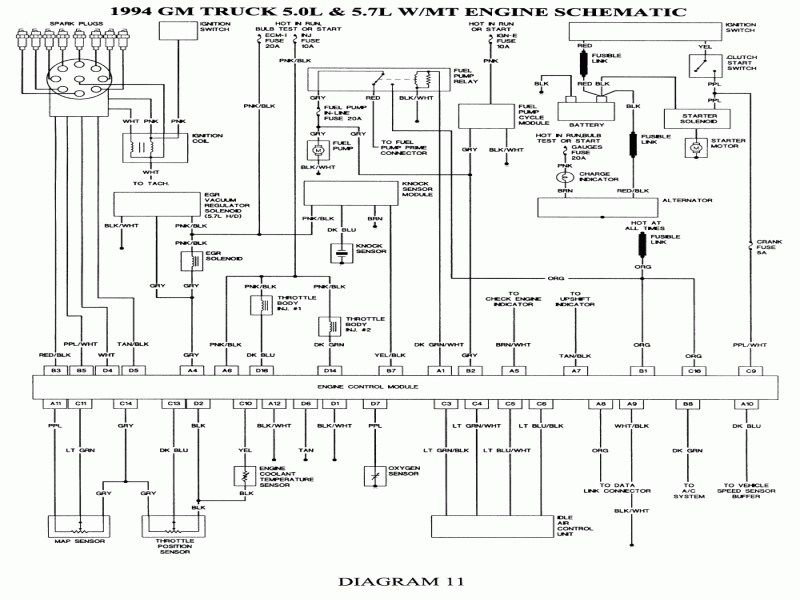
The 1998 Chevy Silverado utilizes a complex wiring harness that's segmented into several main sections. Knowing these sections is key to navigating the diagram effectively:
- Engine Control Module (ECM) Wiring: This covers all the sensors and actuators related to the engine, including fuel injectors, ignition coils, oxygen sensors, and the mass airflow (MAF) sensor. The ECM is the brain of the engine, and its wiring is crucial for optimal performance.
- Transmission Control Module (TCM) Wiring (if equipped with an automatic transmission): Deals with the automatic transmission's solenoids, sensors, and communication with the ECM.
- Body Control Module (BCM) Wiring: Manages various body functions like power windows, door locks, lights, and the anti-theft system.
- Instrument Panel Wiring: Connects the gauges, warning lights, and other components in the dashboard.
- Lighting System Wiring: Includes headlights, taillights, turn signals, and interior lights.
- Charging System Wiring: Covers the alternator, battery, and starter motor.
- Grounding System: Provides the return path for electrical current. A good ground is essential for proper circuit function.
Voltage specifications will vary depending on the circuit, but most operate at 12V DC. Wire gauge (thickness) is also important – thicker wires are used for circuits that carry more current (e.g., starter motor), while thinner wires are used for low-current circuits (e.g., sensors). The diagram will often specify the wire gauge using the AWG (American Wire Gauge) standard.
Decoding the Symbols: Your Wiring Diagram Rosetta Stone
Wiring diagrams are filled with symbols, lines, and color codes. Understanding these is crucial for interpreting the information correctly. Here's a breakdown:
Lines
- Solid Lines: Represent wires. The thickness of the line doesn't necessarily indicate wire gauge.
- Dashed Lines: Often indicate shielded wires or communication buses like the Serial Data line (used for communication between different modules).
Color Codes
Each wire is assigned a color code, typically represented by a two-letter abbreviation (e.g., "RD" for red, "BK" for black, "GN" for green). The first letter indicates the primary color, and the second letter indicates the stripe color (if any). For example, "RD/WH" would be a red wire with a white stripe. These codes are crucial for identifying specific wires within the harness.
Icons
- Resistors: Represented by a zig-zag line.
- Capacitors: Shown as two parallel lines.
- Diodes: Indicated by a triangle with a line at the end. The triangle points in the direction of current flow.
- Fuses: Represented by a wavy line inside a rectangle or a stylized "S" shape.
- Relays: Depicted as a coil and a set of contacts. The coil, when energized, closes the contacts, completing the circuit.
- Grounds: Shown as a series of descending lines, often shaped like an inverted Christmas tree. Different grounding points can be designated as chassis ground or signal ground.
- Connectors: Represented by various shapes, often squares or rectangles. Connector numbers are usually labeled, which are extremely helpful when tracing wires.
- Sensors: Typically a rectangle or circle with an associated letter or number representing its function (e.g., "TPS" for Throttle Position Sensor).
Key Tip: Always refer to the legend on the diagram. It will provide specific definitions for the symbols and abbreviations used in that particular diagram.
How It Works: Following the Electrical Path
The wiring diagram essentially shows you the path of electrical current through the various circuits in your Silverado. Start at the power source (the battery) and trace the circuit through the fuse, switch, relay (if any), component, and finally to ground.
Understanding the concept of series and parallel circuits is crucial. In a series circuit, the components are connected one after the other, so the current flows through each component in turn. If one component fails, the entire circuit is broken. In a parallel circuit, the components are connected side-by-side, so the current can flow through multiple paths. If one component fails, the other components can still function. Most circuits in a vehicle are a combination of series and parallel connections.
Voltage drops are another critical concept. As current flows through a circuit, there will be a voltage drop across each component. Excessive voltage drops can indicate a problem, such as a corroded connection or a damaged wire.
Real-World Use: Basic Troubleshooting Tips
Let's say your headlights aren't working. Here's how you might use the wiring diagram to troubleshoot:
- Consult the diagram: Locate the headlight circuit in the wiring diagram.
- Check the fuse: Identify the fuse for the headlights and check if it's blown. If it is, replace it. If it blows again immediately, there's a short circuit somewhere.
- Trace the wiring: If the fuse is good, trace the wiring from the fuse to the headlight switch, then to the headlights themselves. Look for any breaks, corrosion, or loose connections.
- Test the switch: Use a multimeter to check if the headlight switch is working properly. Set your multimeter to measure continuity. With the switch in the "on" position, you should have continuity between the input and output terminals.
- Check the ground: Ensure the headlights have a good ground connection. A poor ground can cause all sorts of electrical problems.
Remember to use a multimeter to test for voltage and continuity at various points in the circuit. This will help you pinpoint the location of the fault.
Safety First: Handling Risky Components
Working with electrical systems can be dangerous. Always take the following precautions:
- Disconnect the battery: Before working on any electrical circuit, disconnect the negative terminal of the battery to prevent shocks and short circuits.
- Use insulated tools: Use tools with insulated handles to protect yourself from electrical shock.
- Avoid working in wet conditions: Water conducts electricity, increasing the risk of shock.
- Be careful around the airbag system: The airbag system is highly sensitive, and improper handling can cause it to deploy, resulting in serious injury. Refer to the service manual for specific instructions on deactivating and handling the airbag system.
- Capacitors can hold a charge even after the battery is disconnected, which can cause a shock. If you are working near capacitors, take appropriate precautions.
Warning: The starter motor and alternator circuits carry high currents and can be dangerous if mishandled. Exercise extreme caution when working on these circuits.
By combining the wiring diagram with a systematic approach and safety precautions, you can confidently tackle most electrical repairs and upgrades on your 1998 Chevy Silverado. And remember, if you're unsure about anything, it's always best to consult a qualified mechanic.
We have a downloadable version of the complete 1998 Chevy Silverado Wiring Harness Diagram available for you. It's a high-resolution file that you can zoom in on for detailed viewing and print for easy reference.