1999 7.3 Powerstroke Engine Wiring Harness Diagram
For the seasoned DIY mechanic or budding Powerstroke enthusiast, understanding the 1999 7.3 Powerstroke engine wiring harness is paramount. It’s the nervous system of your truck, carrying the critical electrical signals that control everything from fuel injection to sensor readings. Whether you’re troubleshooting a nagging engine problem, planning a performance modification, or simply want a deeper understanding of your rig, having a solid grasp of this wiring diagram is essential.
Purpose of the 1999 7.3 Powerstroke Wiring Diagram
Think of the wiring diagram as a roadmap of your engine's electrical system. It serves several crucial purposes:
- Troubleshooting: When your 7.3L throws a code or experiences drivability issues, the wiring diagram helps you trace circuits, identify potential shorts, opens, or faulty connections.
- Repairing: Accidents happen. Wires get damaged. The diagram guides you through repairing or replacing damaged sections of the harness correctly.
- Modifying: Planning to add aftermarket components like gauges, tuners, or auxiliary lighting? The diagram shows you where to tap into the existing system without causing damage or creating conflicts.
- Understanding: Even if you're not actively working on your truck, studying the diagram deepens your understanding of how the engine's various systems interact.
Key Specs and Main Parts of the 1999 7.3L Wiring Harness
The 1999 7.3 Powerstroke wiring harness isn't a single, monolithic entity. It's composed of several sub-harnesses, each responsible for specific engine functions. Understanding these sections is crucial for targeted troubleshooting:
- Engine Control Harness: This is the heart of the system, connecting the PCM (the engine's computer) to the various sensors and actuators on the engine. It includes connections for the Injector Driver Module (IDM), sensors like the EBP sensor, MAP sensor, ICP sensor, and actuators like the ICP regulator (IPR).
- Injector Harness: This sub-harness specifically connects the IDM to the fuel injectors. Because the 7.3L uses HEUI (Hydraulic Electronic Unit Injection), the wiring here is crucial for precisely timing and controlling fuel delivery.
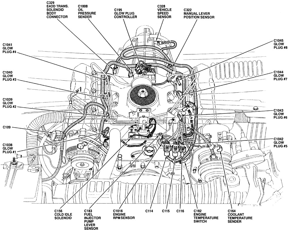
- Glow Plug Harness: Essential for cold starts, this harness powers the glow plugs in each cylinder. Proper function is critical for reliable starting in cold weather.
- Sensor Harnesses: These are smaller harnesses dedicated to specific areas like the transmission, throttle position, and diagnostic connectors.
Key Specs to keep in mind:
- Voltage: The system operates primarily on 12 volts DC, but some circuits, especially those related to the IDM, may see significantly higher voltages (upwards of 100 volts) during operation. Exercise extreme caution when working on these circuits.
- Wire Gauge: Wire gauge (AWG - American Wire Gauge) indicates the wire's current-carrying capacity. Critical circuits like the IDM and glow plugs use heavier gauge wires (e.g., 10 AWG, 12 AWG) to handle higher current loads. Sensor circuits typically use lighter gauge wires.
- Connectors: The harness uses a variety of connectors, including weatherproof connectors, multi-pin connectors, and specialized connectors for the injectors and IDM. Ensuring these connectors are clean, dry, and properly seated is vital.
Understanding Wiring Diagram Symbols
Deciphering a wiring diagram requires understanding its symbology. Here's a breakdown of common symbols:
- Lines: Solid lines represent wires. Dashed lines often represent shielded wires (used for sensitive signals to prevent interference) or internal connections within a component.
- Colors: Each wire is color-coded (e.g., Red/White, Blue/Yellow). The color code identifies the wire's function and allows you to trace it through the harness. The diagram key will list the color abbreviations (e.g., RD/WH, BU/YE).
- Components: Each component (sensor, actuator, relay, etc.) is represented by a symbol. Familiarize yourself with common symbols like resistors (zigzag line), capacitors (parallel lines), diodes (triangle with a line), and relays (coil and switch).
- Grounds: Ground symbols indicate where the circuit connects to the vehicle's chassis, providing a return path for current flow.
- Connectors: Connectors are usually represented by circles or squares with numbers or letters indicating the pin numbers.
- Splices: Splices are points where multiple wires are joined together. They are typically represented by a dot or a more complex symbol indicating the type of splice.
Pay close attention to the diagram's legend or key. It provides definitions for all the symbols and abbreviations used in that specific diagram. No two diagrams are exactly alike.
How the 1999 7.3 Powerstroke Wiring Harness Works
The 7.3L wiring harness functions as a complex communication network. The PCM is the central processor, receiving data from various sensors, processing that data, and sending commands to actuators to control engine operation.
Here's a simplified overview:
- Sensor Input: Sensors like the MAP sensor, EBP sensor, and ICP sensor provide the PCM with real-time information about engine conditions.
- PCM Processing: The PCM uses this sensor data, along with pre-programmed tables and algorithms, to determine the optimal fuel injection timing, duration, and other parameters.
- Actuator Control: The PCM sends signals to actuators like the ICP regulator (IPR) and the fuel injectors to implement its control strategy. The Injector Driver Module (IDM) plays a crucial role in boosting the voltage to the injectors for proper operation.
- Feedback Loops: The system incorporates feedback loops, where the PCM monitors the results of its actions and adjusts its control strategy accordingly. For example, the ICP sensor provides feedback on the actual injection pressure, allowing the PCM to fine-tune the IPR valve to maintain the desired pressure.
Real-World Use: Basic Troubleshooting Tips
Let's look at a common problem and how the wiring diagram can help:
Problem: Engine misfire on cylinder #3.
Troubleshooting Steps:
- Check the code: Retrieve the diagnostic trouble codes (DTCs) using an OBDII scanner. A code specifically related to cylinder #3 injector circuit is a strong indicator of a wiring or injector problem.
- Consult the wiring diagram: Identify the wiring for the cylinder #3 injector in the injector harness section of the diagram. Note the wire colors and pin numbers at the IDM and injector connector.
- Inspect the wiring and connectors: Visually inspect the wiring harness for damage, chafing, or corrosion, especially near the injector connector and where the harness runs along the engine. Check the injector connector for loose or corroded pins.
- Perform continuity tests: Use a multimeter to check the continuity of the wires between the IDM connector and the injector connector. Disconnect both ends before testing. A lack of continuity indicates a broken wire.
- Check for shorts to ground: With the injector and IDM disconnected, use the multimeter to check for shorts between the injector wires and ground. A short to ground can damage the IDM or cause a misfire.
Additional Tips:
- Use a wiring diagram specific to your model year. There can be subtle differences between years.
- Take your time and be methodical. Trace circuits carefully and double-check your work.
- Use a high-quality multimeter and test leads.
- Consider using a wire tracker or toner to locate wires within the harness.
Safety Precautions
Working with automotive electrical systems can be dangerous. Here are some essential safety precautions:
- Disconnect the battery: Always disconnect the negative battery terminal before working on the wiring harness. This prevents accidental shorts and electrical shocks.
- High-Voltage Circuits: Be extremely cautious when working on circuits connected to the IDM. These circuits can carry voltages exceeding 100 volts, which can be lethal. Never probe these circuits with the engine running.
- Airbag Systems: Be aware of the location of airbag sensors and wiring. Mishandling or damaging these components can cause the airbags to deploy unexpectedly.
- Fuel System: When working near fuel lines or injectors, take precautions to prevent fuel spills and fire hazards.
Remember, if you're uncomfortable working on the electrical system, it's always best to consult a qualified mechanic.
To aid you in your troubleshooting and repair efforts, we have a 1999 7.3 Powerstroke engine wiring harness diagram available for download. This comprehensive resource will give you the detailed information you need to diagnose and fix electrical problems on your truck. It's a valuable tool for any serious 7.3L Powerstroke owner or mechanic.