
1999 Ford F150 4.6 Vacuum Line Diagram
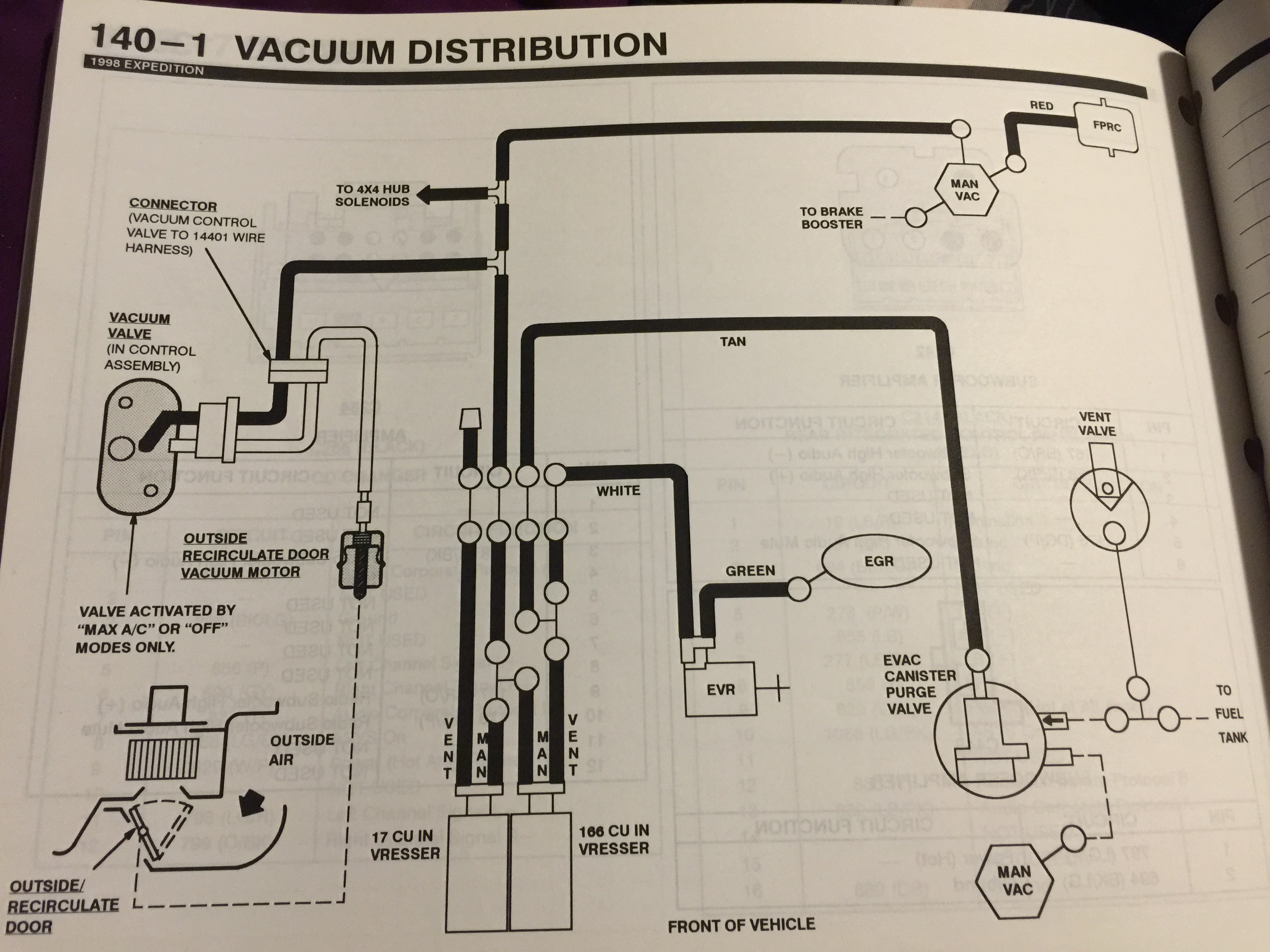
Alright, let's dive into the often-overlooked but critically important world of vacuum lines on your 1999 Ford F150 with the 4.6L engine. This isn't just about knowing where hoses go; understanding the vacuum system is key to diagnosing a range of engine issues, improving performance, and even undertaking certain modifications with confidence. We'll break down the vacuum line diagram piece by piece, so you'll be equipped to tackle repairs and maintenance with a solid understanding.
Why Bother with the Vacuum Line Diagram?
Think of the vacuum system as your engine's nervous system – it connects and controls various components, influencing everything from fuel efficiency to emissions control. A faulty vacuum line can cause a surprising number of problems: rough idling, poor acceleration, increased fuel consumption, vacuum leaks (hissing sounds), and even trigger the dreaded check engine light. Having the vacuum line diagram handy is crucial for:
- Troubleshooting: Quickly pinpointing the source of a vacuum leak or misconnected hose.
- Repairing: Replacing brittle, cracked, or damaged lines correctly.
- Understanding System Function: Gaining a deeper insight into how different engine components interact.
- Modifications: Ensuring any performance upgrades or add-ons integrate properly with the existing vacuum system.
- Restoration: Correctly restoring a classic F150 to its original configuration.
Key Specs and Main Vacuum System Components
Before we get into the diagram itself, let's identify the major players in the 4.6L F150 vacuum system:
- Intake Manifold: The heart of the system. This is where engine vacuum is generated as the pistons move down on their intake stroke.
- Vacuum Reservoir (or Canister): A storage container that maintains a steady vacuum supply, especially when engine vacuum fluctuates (e.g., during acceleration).
- PCV (Positive Crankcase Ventilation) Valve: A one-way valve that vents crankcase gases into the intake manifold to be burned, reducing emissions and preventing pressure buildup in the engine.
- EGR (Exhaust Gas Recirculation) Valve: This valve recirculates a portion of the exhaust gas back into the intake manifold, lowering combustion temperatures and reducing NOx emissions. The EGR valve is often vacuum-operated.
- EVAP (Evaporative Emission Control) System: This system captures fuel vapors from the fuel tank and prevents them from escaping into the atmosphere. It typically involves a charcoal canister and various valves controlled by vacuum.
- Vacuum Brake Booster: Provides power assist to the brake system, reducing the effort required to apply the brakes.
- HVAC (Heating, Ventilation, and Air Conditioning) Controls: Vacuum lines are used to control the blend doors and mode doors within the HVAC system, directing airflow to different vents.
- Throttle Body: While not directly part of the vacuum *generating* system, the throttle body affects engine vacuum based on its position (throttle opening).
Decoding the Vacuum Line Diagram: Symbols and Conventions
Vacuum line diagrams aren't exactly works of art, but they are packed with information. Here's how to interpret the common symbols and conventions:
- Solid Lines: Represent actual vacuum lines (hoses).
- Dotted Lines: Indicate vacuum lines that might be present on some models but not others, or perhaps lines that are part of a sub-system not always included.
- Arrows: Show the direction of vacuum flow. This is critical! Always trace the arrows to understand where vacuum is coming from and where it's going.
- Colors: Ford often used different colored vacuum lines (e.g., red, green, black) to differentiate them. The diagram should provide a key indicating which color corresponds to which line. If colors are faded or missing on your truck, the diagram is even *more* important.
- Connectors/Fittings: Depicted as small circles or squares where lines connect to components.
- Vacuum Check Valves: Represented by a symbol that looks like a diode (triangle with a line). They allow vacuum to flow in only one direction. These are essential for maintaining vacuum in certain parts of the system.
- Vacuum Motors/Actuators: These are often shown as a small circle with a piston symbol inside. They convert vacuum into mechanical motion (e.g., for controlling blend doors).
- Component Labels: Abbreviations or short descriptions identifying each component (e.g., "PCV," "EGR," "VAC RES").
Important Note: Due to minor variations in production and model years, always double-check that the diagram you are using *precisely* matches your specific 1999 F150 4.6L configuration. Small differences can make a big impact.
How the Vacuum System Works: A Simplified Explanation
The engine's intake manifold creates a vacuum as the pistons move downward during the intake stroke. This vacuum is essentially "negative pressure" and is used to operate various engine components. The vacuum reservoir acts as a buffer, ensuring a consistent vacuum supply even when engine vacuum fluctuates. The PCV system uses vacuum to draw crankcase gases into the intake, where they are burned. The EGR valve is opened by vacuum, allowing exhaust gas to be recirculated. The EVAP system uses vacuum to purge fuel vapors from the charcoal canister. The brake booster uses vacuum to amplify braking force. And the HVAC system uses vacuum to control airflow.
The key to understanding the system is to trace the vacuum lines from the intake manifold (the source of vacuum) to each component. Ask yourself: What is this component doing? What would happen if it didn't receive vacuum?
Real-World Use: Basic Troubleshooting Tips
Here are some common vacuum system issues and how to use the diagram to troubleshoot them:
- Vacuum Leak (Hissing Sound): Use a length of hose as a "stethoscope" to listen for the source of the hissing. The diagram will help you identify which lines are in the area of the leak.
- Rough Idle: A vacuum leak can cause a lean air-fuel mixture, leading to a rough idle. Inspect all vacuum lines for cracks, breaks, or loose connections. Pay close attention to lines connected to the PCV valve, EGR valve, and intake manifold.
- Poor Acceleration: A vacuum leak can also reduce engine power and responsiveness. Check the vacuum lines connected to the EGR valve and the fuel pressure regulator (if applicable).
- Check Engine Light (CEL): Scan the OBD-II system for diagnostic trouble codes (DTCs). Many codes relate to vacuum system issues (e.g., lean codes, EGR codes, EVAP codes). The diagram will help you pinpoint the likely causes of the code.
- HVAC Problems: If your climate control system isn't working correctly (e.g., air only comes out of the defrost vents), a vacuum leak in the HVAC control system is a likely culprit. The diagram will show you the vacuum lines connected to the HVAC control module and the vacuum actuators that control the blend doors.
Example: Let's say you have a P0401 code (Insufficient EGR Flow). Using the diagram, you can trace the vacuum line that controls the EGR valve. Check the line for leaks, cracks, or blockages. Also, check the EGR valve itself to see if it's stuck open or closed.
Safety Considerations
Working on the vacuum system is generally safe, but there are a few things to keep in mind:
- Hot Engine: Always allow the engine to cool down completely before working on the vacuum system. The exhaust manifold and other engine components can be extremely hot.
- Fuel Lines: Be careful when working near fuel lines. Avoid smoking or using open flames.
- Sharp Edges: Some engine components have sharp edges. Wear gloves to protect your hands.
- Battery Disconnect: While not always necessary, disconnecting the negative battery cable can help prevent accidental electrical shorts.
Specific Caution: The EVAP system deals with fuel vapors. Be extremely careful when working on this system. Avoid creating sparks or open flames.
With a little patience and the right information (like this guide and the vacuum line diagram), you can successfully troubleshoot and repair vacuum system issues on your 1999 Ford F150 4.6L. Remember to take your time, double-check your work, and don't be afraid to consult with a professional mechanic if you get stuck.